
Squeegee device with U-shaped carriage

a squeegee and carriage technology, applied in the direction of printing presses, rotary presses, printing presses, etc., can solve the problem of insufficient pressure applied to the pressure cylinder to lift the squeegee, and achieve the effect of facilitating the adjustment of the squeegee angle, reducing the complexity of control, and large pivoting angles

Inactive Publication Date: 2009-03-17
THIEME GMBH & CO KG
View PDF19 Cites 12 Cited by
  • Summary
  • Abstract
  • Description
  • Claims
  • Application Information

AI Technical Summary

Benefits of technology

[0004]An object of the invention is to provide a compact and reliable squeegee assembly for a screen printing machine.
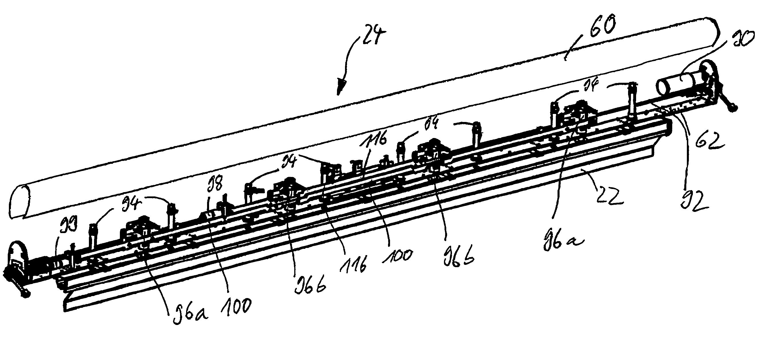
[0015]Advantageously, the carriages provided are a printing squeegee carriage and, in parallel thereto, a flood squeegee carriage. Adjustable limit stops are provided in the flood squeegee carriage to limit the stroke of the flood squeegee relative to the printing table. Advantageously, the one or more limit stops in the central area of the printing table can be adjusted independently from the limit stops in the edge area of the printing table. This enables a so-called cambering, which corresponds to a downward deformation of the squeegee in the center of the printing table to compensate any sagging of the screen fabric in large printing screens. The limit stops are advantageously adjustable by means of a stroke limiting device, which is arranged within the U-shaped profile of the flood squeegee carriage and has a servomotor and an opposite limit stop that can be displaced in a slotted link. Using an opposite limit stop displaceable in a slotted link makes it possible to achieve a highly precise adjustment of the opposite limit stop and, moreover, also to apply very large counterforces.

Problems solved by technology

When the squeegee is lifted or pressed down during the printing process, for example, only sufficient pressure to lift the squeegee is applied to the pressure cylinders.

Method used


Image

  • Squeegee device with U-shaped carriage
  • Squeegee device with U-shaped carriage
  • Squeegee device with U-shaped carriage

Examples


Embodiment Construction

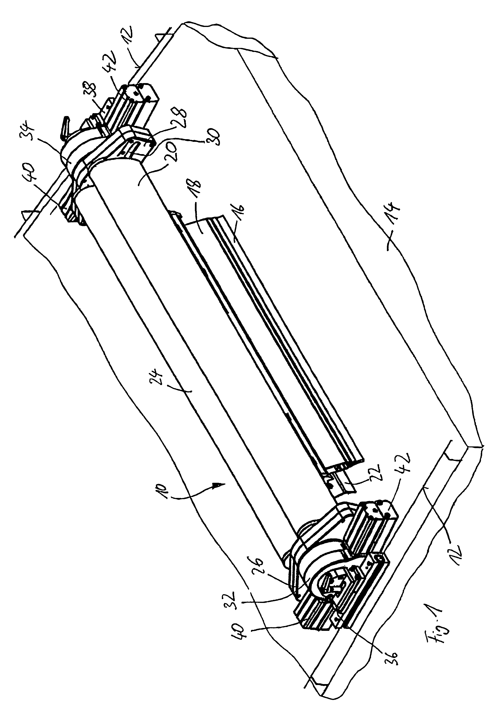
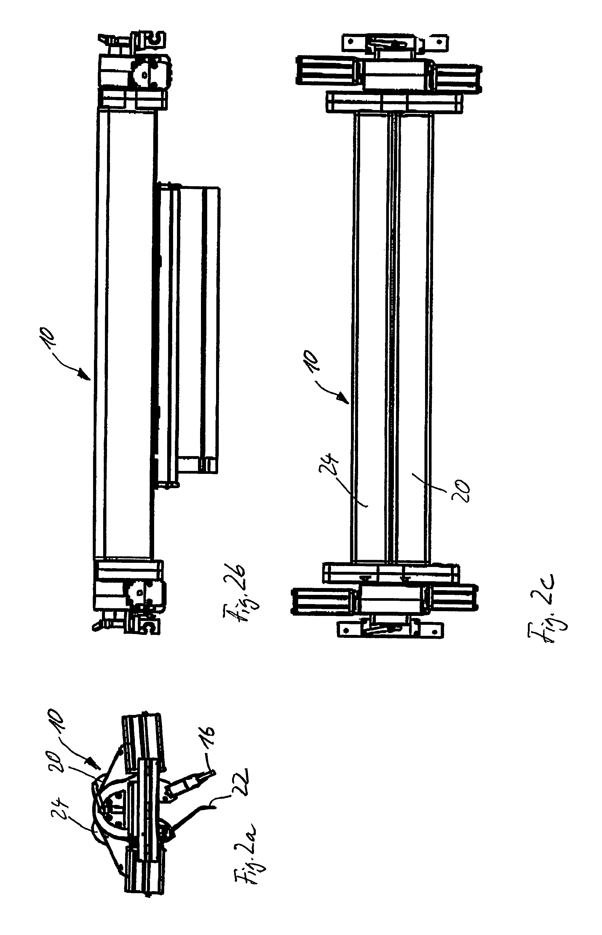
[0029]In the representation of FIG. 1, a screen printing machine is depicted schematically with only the squeegee assembly 10 being shown non-schematically. The squeegee assembly 10 can be displaced across a printing table 14 along guide rails 12. A printing screen (not depicted) may be arranged above the printing table 14 in a manner known per se, and a sheet of paper, for example, lying on the printing table 14 is printed with the ink pressed through the printing screen as the squeegee assembly 10 moves across the printing table 14. The schematically indicated guide rails 12 are spaced at a distance above the printing table 14. The squeegee assembly 10 is moved along the guide rails 14 by means of a drive (not depicted).

[0030]The squeegee assembly 10 for the screen printing machine has a printing squeegee 16 mounted to a squeegee holder 18, which in turn is connected to a printing squeegee carriage 20. In addition, a flood squeegee 22 is provided, which is disposed on a flood sque...


PUM


Abstract

Squeegee assembly for a screen printing machine with a printing table, wherein the squeegee assembly has at least one squeegee, one squeegee holder and at least one support displaceable across the printing table, wherein the squeegee is held on the support by means of the squeegee holder and can be pressed against the printing table by pressure cylinders, characterized in that the support has a U-shaped profile, and at least the cylinder sections of the pressure cylinders are accommodated within the U-shaped profile.

Description

[0001]This application claims priority to German patent application no. DE 20 2005 007 281.8, filed May 2, 2005, and the benefit under 35 U.S.C. §119(e) of U.S. provisional patent application Ser. No. 60 / 684,170, filed May 25, 2005, the disclosures of which are expressly incorporated by reference herein.BACKGROUND AND SUMMARY OF THE INVENTION[0002]The invention relates to a squeegee assembly for a screen printing machine with a printing table. The squeegee assembly has at least one squeegee, a squeegee holder and at least one carriage that is displaceable across the printing table. The squeegee is held on the carriage by the squeegee holder and can be pressed against the printing table by pressure cylinders. The invention further relates to a screen printing machine with a squeegee assembly according to the invention.[0003]The European Patent EP 0 315 817 B1 discloses a screen printing machine with a printing table and a squeegee that is displaceable across the printing table. A squ...

Claims


Application Information

Patent Timeline
Patent Type & Authority Patents(United States)
IPC IPC(8): B41L13/18
CPCB41F15/44
Inventor WEBER, DIETMARGOETZ, HARRY
Owner THIEME GMBH & CO KG
Learn More