Stethoscope cleaning assembly

a technology of cleaning assembly and stethoscope, which is applied in the field of stethoscope cleaning assembly, can solve the problems of requiring the availability of wipes, and generally not being integrated into routine physician practice, so as to facilitate replacement and/or maintenance, avoid this potential serious contamination risk, and avoid the effect of contamination

Active Publication Date: 2009-03-17
SEEDLINGS LIFE SCI VENTURES
View PDF20 Cites 27 Cited by
  • Summary
  • Abstract
  • Description
  • Claims
  • Application Information

AI Technical Summary

Benefits of technology

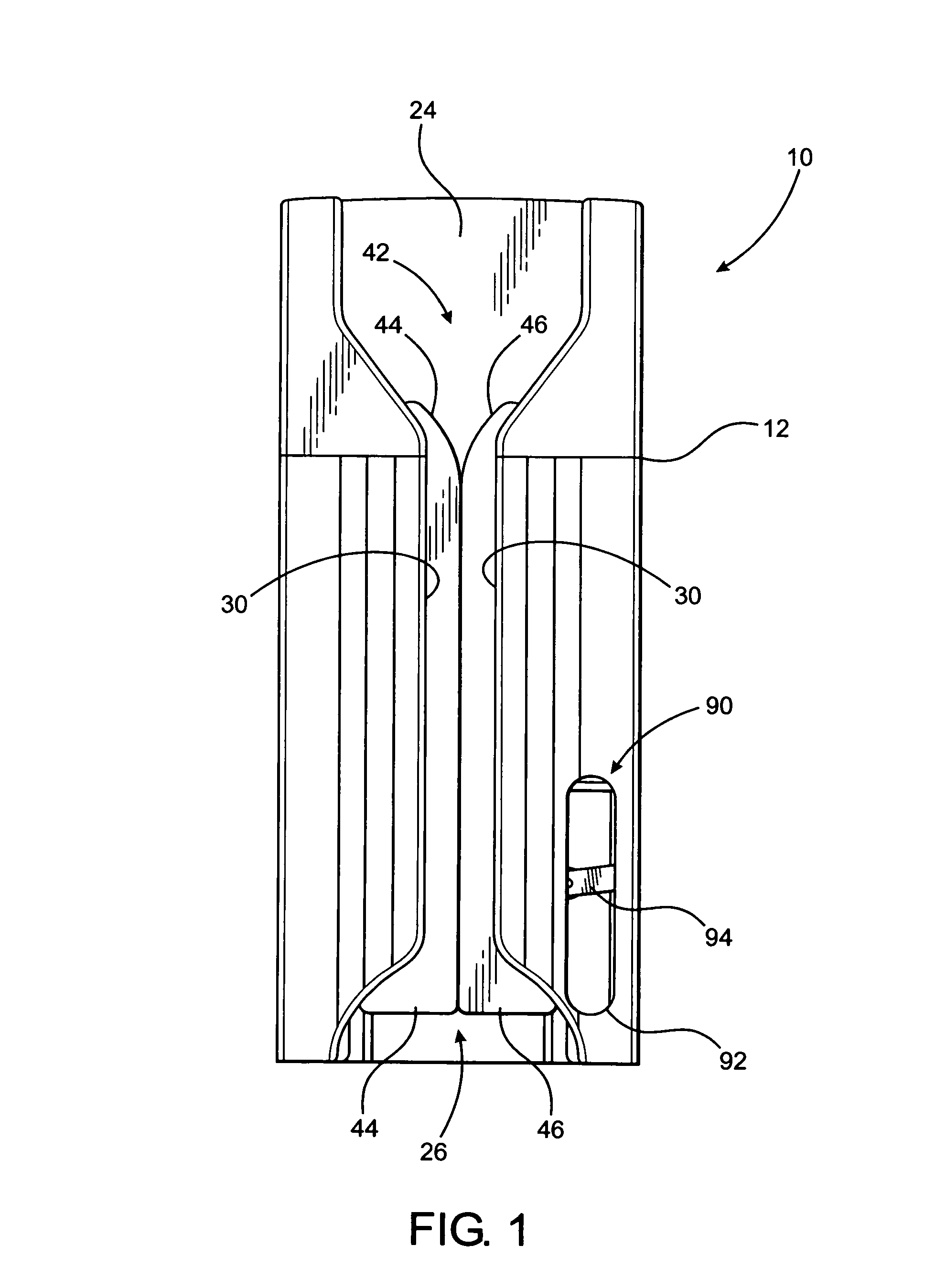
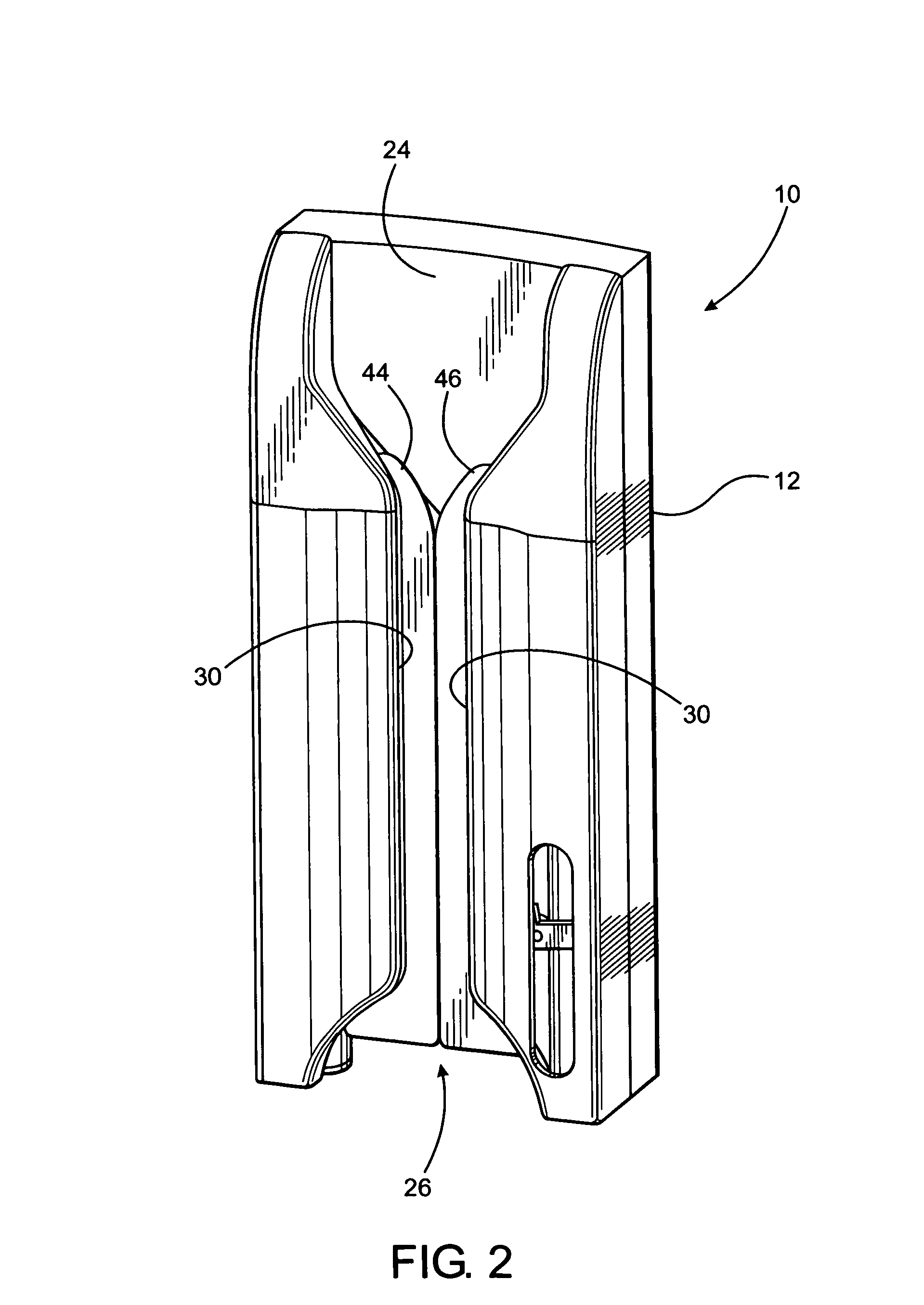
[0024]When the head portion is passing along the path of travel, the diaphragm, supporting rim and other contiguous parts of the head portion are segregated from the exterior of the housing and ambient conditions associated therewith. It is further emphasized that in order to increase the efficiency and effectiveness of the cleaning procedure, the housing as well as the path of travel and other components to be described in greater detail hereinafter are selectively structured, disposed and dimensioned so as to facilitate passage of the head along the path of travel and between the entrance and exit portions by means of a single “swiping” action. Such a swiping action eliminates the requirement or need for a successive, reciprocal or repetitive type of movement of the head portion on the interior of the housing and along the path of travel in order to accomplish an effective cleaning thereof as intended.
[0027]In a most preferred embodiment of the present invention the versatility, safety and efficiency of the cleaning assembly is further demonstrated by the elimination of the need for any supplemental power. Supplemental power, in the form of an electrically driven motor, has been employed in other devices with a similar purpose. The use of an electrically driven motor poses to the user the risks of malfunction, fire, electrical shock or explosion. The risk of fire and explosion are even greater when considering that the vast majority of preferred cleaning fluids for equipment cleaning are alcohol based and flammable. Other known cleaning assemblies, while not employing a motor or flammable cleaning fluid, do utilize high voltage electricity (200-1,000 volts), which exposes the user to the risk of electrocution. Also, known devices of this type pose a risk of UV light exposure to the user or others in the vicinity of the device, when in use.
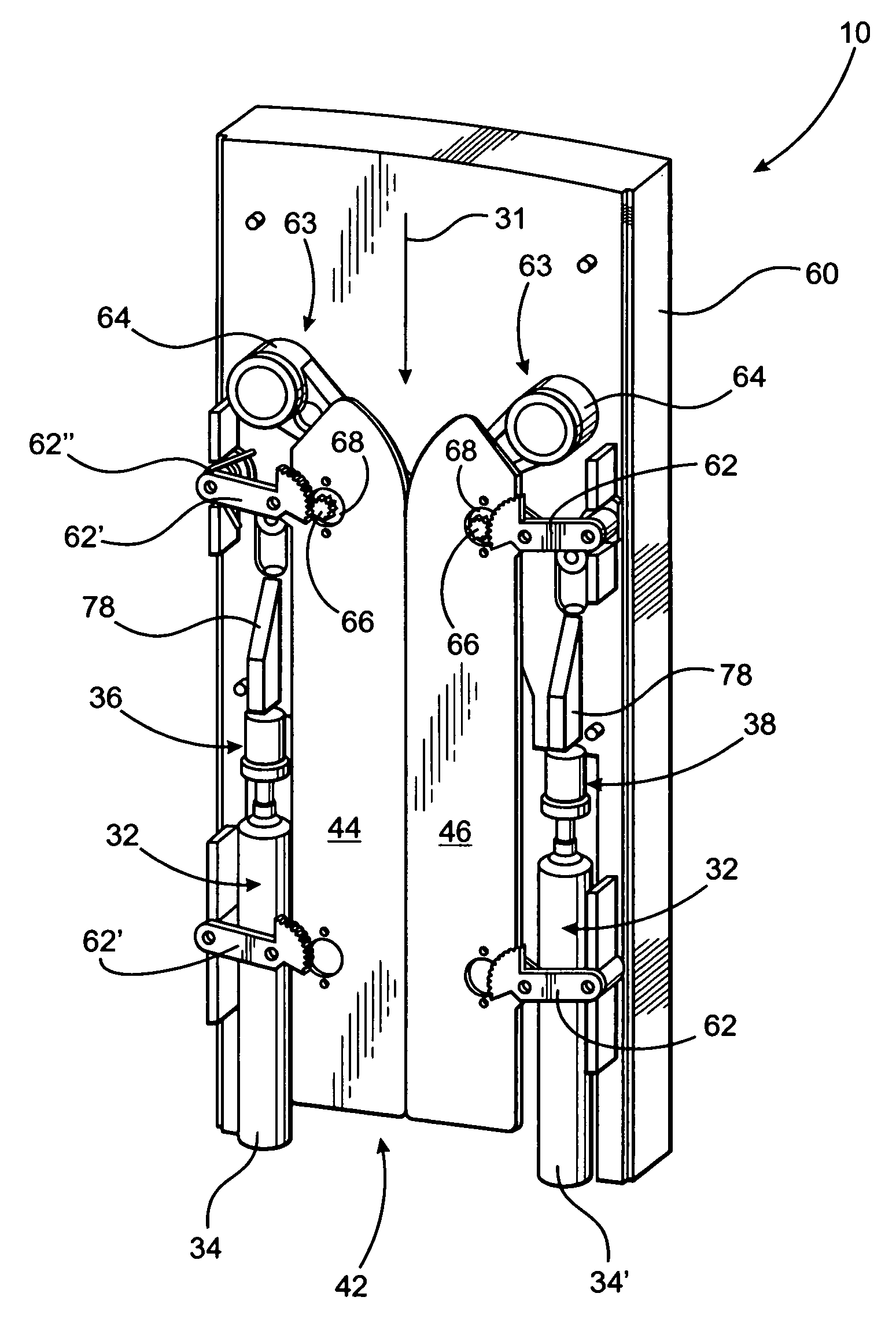
[0029]Moreover, the applicator assembly is disposed and structured to apply cleaning fluid to the diaphragm and other appropriate portions of the head of the stethoscope, which contact the applicator assembly as the head of the stethoscope passes along the path of travel. The applicator assembly is also disposed and structured to provide a cleaning and possibly mildly abrasive action to the head portion as well as remove excess cleaning fluid therefrom. The above set forth cleaning procedure is accomplished on the interior of the housing prior to removal of the head portion through the aforementioned exit. In addition, the applicator assembly, in at least some of the embodiments of the present invention, may be removably mounted on the interior of the housing, as part of a removable, replaceable cartridge, so as to facilitate replacement and / or maintenance thereof when needed.
[0030]Accordingly, the structural and operative features of the cleaning assembly of the present invention allow for the utilization of a single swiping action which is unique and distinguishable from known or conventional stethoscope cleaning assemblies. Moreover, in a single, smooth, one-handed, unidirectional swiping maneuver, the operator brings the stethoscope head into the interior chamber of the housing of the device. In the same swiping maneuver, the operator brings the stethoscope head in contact with the one or more activating members thereby forcibly driving the one or more activating members into an operative position to actively dispense cleaning fluid onto the aforementioned applicator assembly. In the same swiping maneuver, the operator brings the diaphragm and rim portions of the stethoscope head into operative contact with the various components of the applicator assembly. This serves to distribute cleaning fluid across the diaphragm and rim in such a manner as to disinfect the diaphragm and rim. In the same swiping maneuver, the operator brings the diaphragm and rim portions of the stethoscope head into activating contact with a cleaning member of the applicator assembly, which serves to remove dirt, debris and contaminants from the stethoscope diaphragm and rim. In the same swiping maneuver, the operator brings the diaphragm and rim portions of the stethoscope head into activating contact with an additional member of the applicator assembly that serves to remove excess cleaning fluid, thereby at least partially drying the diaphragm and rim. In the same swiping maneuver, the operator brings the stethoscope head further along the path of travel until it exits the interior chamber of the housing. The end result of this single, smooth, one-handed, unidirectional swiping maneuver is a disinfected, cleaned and at least partially dried diaphragm and rim of the stethoscope head.
[0031]Accordingly, the structural and operative features of the stethoscope cleaning assembly of the present invention overcome many if not all of the disadvantages of known or conventional devices. More specifically, such conventional devices typically require the use of two hands, one to hold the stethoscope and the other to depress or push an activating structure on the conventional cleaning devices. Any lever or button located externally to a conventional cleaning device may become infected or contaminated by the external environment. If a user touches an external lever or button with a hand, the user's hand may become infected or contaminated with potentially dangerous microorganisms located on the lever or button. The present invention avoids this potential serious contamination risk by the elimination of any external activating buttons, levers or like members. Yet other conventional or known cleaning assemblies require a separate wiping maneuver to dry the stethoscope head on a pad external to the device. An external pad is less advantageous in that this pad is also susceptible to infection and contamination by the external environment. This infection and contamination may be spread to the user's stethoscope during the drying maneuver. The present invention, which lacks an external pad or like structure avoids this potentially serious contamination risk.
[0032]Therefore, the cleaning assembly of the present invention comprises structural and operative features which facilitate the cleaning, and / or disinfecting of the diaphragm, rim and other appropriate portions of the head of the stethoscope in a quick, effective and reliable manner so as to overcome many of the disadvantages and problems associated with known or conventional cleaning assemblies intended for this purpose.

Problems solved by technology

However, because of time demands, emergency situations and other situations which frequently occur, a health care provider may only perform a minimal cleaning of the instrument on an occasional basis.
Although, these cursory cleaning procedures may be effective, they are burdensome, time consuming and require the ready availability of these wipes.
Furthermore, while available and inexpensive, these wipes have generally not been integrated into routine physician practice.
However, many known or conventional devices, while being at least minimally operative to accomplish their intended purpose, also suffer from numerous disadvantages.
Such disadvantages generally relate to accomplishing an effective cleaning, disinfecting or possible sterilization of the instrument and the fact that many of such known cleaning devices are difficult or too time consuming for convenient use.
The transfer of pathogenic bacteria from one patient to another is a major cause of healthcare associated infections.
However, the majority of healthcare workers do not clean or disinfect their stethoscope after each patient encounter.
Common reasons for not cleaning or disinfecting stethoscopes are that the alcohol pads and swabs are not readily available, are messy, time consuming to use and require disposal.
However, the Centers for Disease Control and Prevention also recommends that for all patients receiving care in a hospital, an item of patient care equipment must not be reused on another patient until it has been cleaned and reprocessed appropriately.
Further, any such cleaning device that is located in a patient's room or in an examination area may, over time, have its exterior surface contaminated by pathogenic bacteria.

Method used


Image

  • Stethoscope cleaning assembly
  • Stethoscope cleaning assembly
  • Stethoscope cleaning assembly

Examples


Embodiment Construction

[0050]As shown in the accompanying drawings, the present invention is directed to a cleaning assembly 10 for the head of a stethoscope.

[0051]The cleaning assembly 10 includes a housing 12 having a hollow interior of sufficient dimension and configuration to contain a plurality of operative components to be described in greater detail hereinafter. As also described, the cleaning assembly 10 is specifically structured to “clean” the diaphragm, supportive rim and other exposed portions of the head which are brought into direct contact with a patient's body. More specifically, the head portion 14 as represented in FIG. 10 includes a diaphragm 16 and supportive and / or surrounding rim portion 18 generally associated with an exposed face or patient contacting portion 20 of the stethoscope head 14. Additional features relating to the manipulation or placement of the head 14 comprise the structuring of the housing 12, as well as other operative components associated therewith, which facilita...


PUM


Abstract

An assembly structured to clean the head portion of a stethoscope comprising a housing including a path of travel along which the head portion passes during cleaning. A supply of cleaning fluid is associated with a dispensing assembly which is cooperatively disposed relative to an activating assembly. The activating assembly is manually operated due to moveable engagement with the head portion as it travels along the path of travel. The activating assembly is thereby operatively positioned to activate the dispenser assembly when engaged by the head portion as it passes along the path of travel. The dispensing assembly delivers the cleaning fluid to an applicator assembly which distributes the cleaning fluid to the head portion and facilitates the cleaning thereof and removal of excess cleaning fluid there from.

Description

CLAIM OF PRIORITY[0001]The present application is a continuation-in-part patent application of previously filed, application having Ser. No. 11 / 728,207, filed on Mar. 23, 2007, now U.S. Pat. No. 7,406,973, incorporated herein in its entirety by reference.BACKGROUND OF THE INVENTION[0002]1. Field of the Invention[0003]This invention is directed to an assembly structured to clean the head portion of a stethoscope comprising a housing including a path of travel along which the head portion passes during cleaning. A supply of cleaning fluid is associated with a dispensing assembly which is cooperatively disposed relative to an activating assembly. The activating assembly is operatively positioned to activate the dispenser assembly when engaged by the head portion as it passes along the path of travel. The dispensing assembly delivers the cleaning fluid to an applicator assembly which distributes the cleaning fluid to the head portion and facilitates the cleaning thereof and removal of e...

Claims


Application Information

Patent Timeline
Patent Type & Authority Patents(United States)
IPC IPC(8): B08B3/00B08B3/12
CPCA61B19/34A61B7/02A61L2/18A61B90/70
Inventor PERLMAN, MICHAELSELLERS, JAMES M.RUBIN, KEITHCARDINALI, MATHEWCOLE, MICHAEL R.PERLMAN, SIDNEY
Owner SEEDLINGS LIFE SCI VENTURES
Why Eureka
Try Eureka