Multi-chamber container and cap therefor

a multi-chamber, container technology, applied in the direction of transportation and packaging, internal fittings, tamper-indication equipment, etc., can solve the problems of few commercially available containers, danger of foil or other residue fragments falling into the mixed components, etc., and achieve the effect of convenient dispensing

Inactive Publication Date: 2009-03-17
SEISMIC SOLUTIONS LLC +4
View PDF52 Cites 96 Cited by
  • Summary
  • Abstract
  • Description
  • Claims
  • Application Information

AI Technical Summary

Benefits of technology

[0009]In a further embodiment, the device consists of a similar cap or housing that is provided with a built in liquid dispensing attachment (sipper) that allows the use of the mixed components without removing the cap or housing from the main package.
[0015]In an embodiment, the dispensing tip may include apertures formed therein for dispensing of the component from the second chamber to the first chamber. In an embodiment, the dispensing tip may include a transverse base member having a generally conical shaped upper surface to allow for the component to be dispensed easily through the open end of the cap. In an embodiment, the cap body may include an outer collar forming a threaded receptacle for mounting the cap onto the container main body. In an embodiment, the cap body may include threads having vents formed therein. In an embodiment, storage condition may provide for an air tight seal for the second chamber.
[0016]In an embodiment, the plunger may include a locking lug and the cap body includes a key way for engaging the locking lug in order to prevent axial rotation of the plunger. In an embodiment, the lid may form a soft shaped target surface. In an embodiment, the dispensing tip may include a labyrinth seal that restricts air and moisture from passing into the second chamber. In an embodiment, the dispensing tip may include a dielectric seal in the storage condition. In an embodiment, the dielectric seal may be adjustably securable so that during manufacture of the container the amount of energy directed toward the dispensing tip may be controlled in order to adjust the pull strength of the seal. In an embodiment, the container and cap may provide for a modular system that may be removed from the container main body without adjusting the plunger from the storage condition and preventing the dispensing tip to move from the closed position so that the cap may be shipped separate from the container main body and also so that the volume of the liquid in the first chamber can be adjusted while the cap is removed and without affecting the amount of component within the second chamber of the cap.

Problems solved by technology

Also prior art concerning containers with two compartments, separating two ingredients to be mixed before consumption, exist; but few if any of these containers are commercially available mostly because of complicated parts, difficulty of filling and high manufacturing cost.
Whether piercing tips or cutters are used to remove the seal between compartments, there is always the danger of having fragments of foil or other residue fall into the mixed components.

Method used


Image

  • Multi-chamber container and cap therefor
  • Multi-chamber container and cap therefor
  • Multi-chamber container and cap therefor

Examples


first embodiment

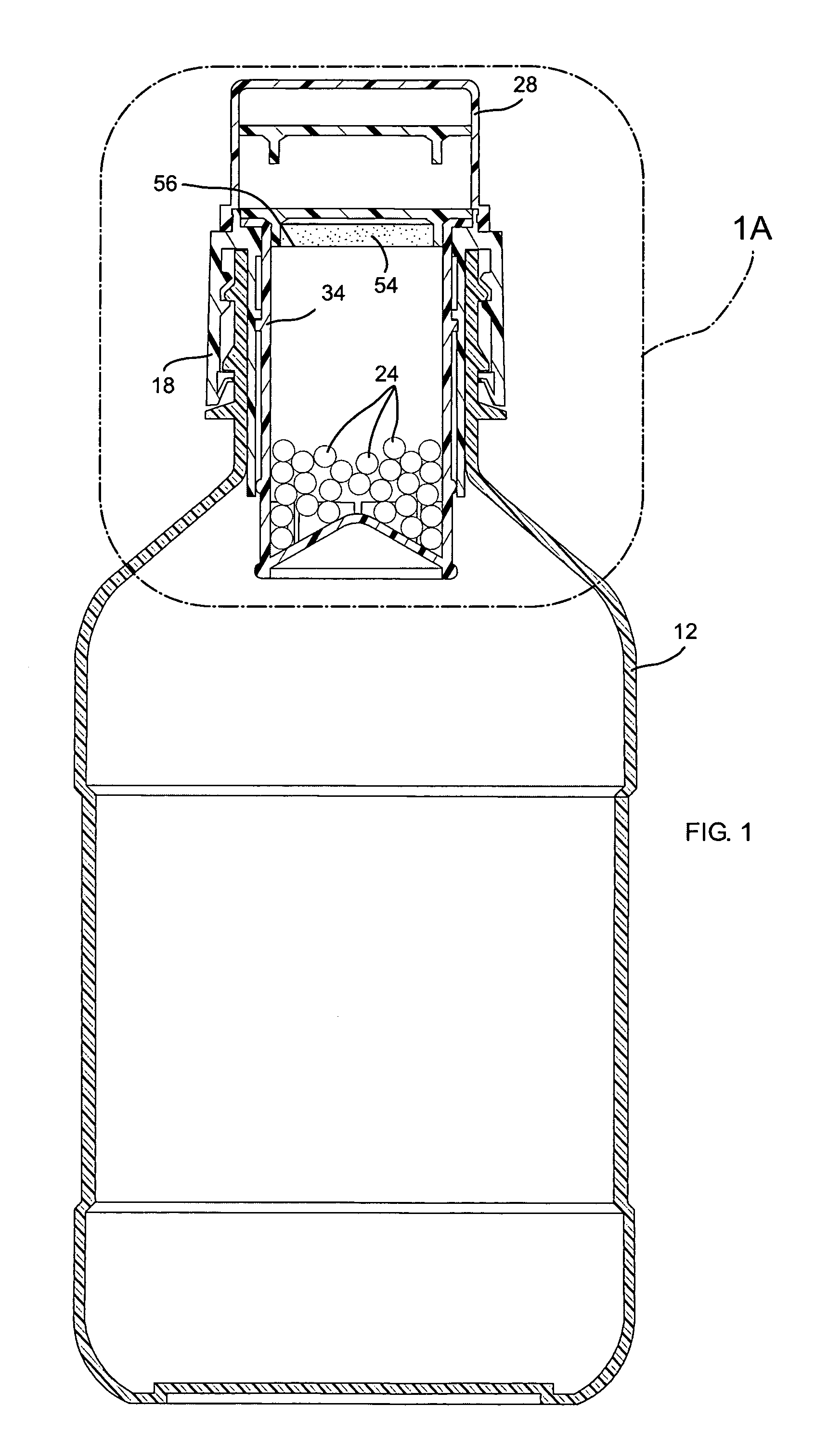
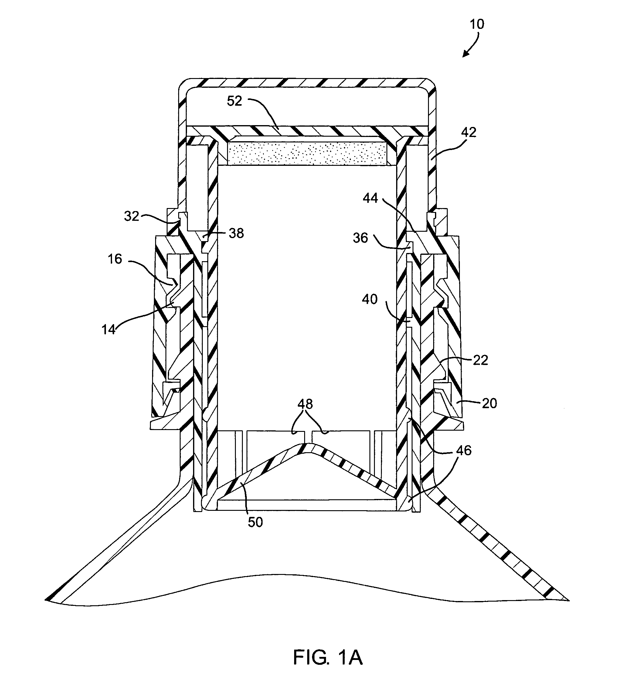
[0042]the invention is depicted with respect to FIGS. 1-4B. In FIG. 1, the dispensing closure or cap 10 is shown in use with a plastic container 12 which contains a main component such as water or a variety of different fluids. The container 12 or main package has a threaded neck 14 to which the dispensing closure 10 is mounted using internal threads 16, FIG. 4, included in the container cap or body 18. The container cap 18 or cap is serrated 80, (FIG. 4), in order to facilitate the assembly and disassembly of the dispensing closure 10 to the container 12.

[0043]The container cap 18 is provided with a tamper proof ring 20 that locks behind a collar 22 built into the container neck 14, when the dispensing closure 10 is threaded all the way in. When removing the dispensing closure 10 after the first component 24 has been added to the container 12, the tamper proof ring 20 remains locked behind the collar 22 and the unscrewing motion provides enough force to break thin protrusions 26FIG...

second embodiment

[0076]In an embodiment, the invention may include a pull cap (with or without sipper). This embodiment of the invention is similar to the first aforementioned two preferred embodiments, except that the dispensing of the first component into the supplemental component motion is reversed and a pull action is used instead of push. Removing the protective cap and pulling a plug up above the narrow part of a funnel shaped first component holder, allows the first component to be dispensed into the main package. this alternate version provides a liquid dispensing nozzle or sipper that allows utilization of the mixed components without removing the closure from the main package.

third embodiment

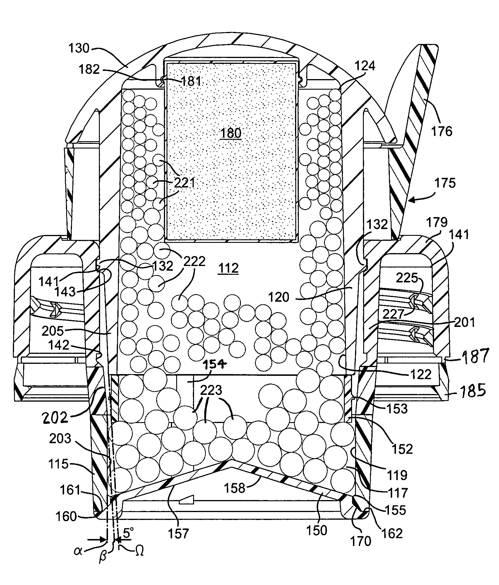
[0077]Turning to FIGS. 8-13, the present invention is depicted. A container main body 100 forms a first chamber 101. In an embodiment, the container main body 100 may have the shape of well-known isotonic beverage or energy drink bottles and may be manufactured according to well-known methods of manufacturing such bottles. In an embodiment, the container main body 100 may be formed of a PET material and is filled by a room temperature or cooler fill process. The container main body 100 includes an opening 104 formed by a neck 106. In a preferred embodiment, the neck 106 is threaded.

[0078]A container cap 110 is mounted to the neck 106. In the preferred embodiment, the container cap 110 is threaded onto the neck 106. The cap 110 forms a second chamber 112 (see FIG. 11) that stores a component. In a preferred embodiment, the second chamber provides an air-tight seal to protect the component and allows the cap 110 or container 100 to be stored on a shelf without degradation or spoilage ...


PUM


Abstract

A dispenser comprises a housing that has a removable tamper proof protective cap and tamper proof ring and is threaded to a container. The container, which is the main package, holds the supplemental component. The housing holds the first component into a plunger type chamber in a fully retracted position and is sealed from the supplemental component. The chamber has a delivery end that is closed before use. When pushed all the way in, the chamber's delivery end becomes open and delivers the first component into the main package.

Description

[0001]This application claims the benefit of the filing date of provisional application Ser. No. 60 / 624,931, filed Nov. 4, 2004.BACKGROUND OF THE INVENTION[0002]This invention concerns a dispensing closure such as a container; especially containers that have at least two chambers that may be used to keep at least two components, such as a liquid and a powder or tablets, separated until time for use.[0003]Many different styles of caps, lids and closures have been well documented and described in the prior art. They include tamper proof closures, caps that seal the container using a check valve taking advantage of the squeeze action of a flexible bottle to create the pressure differential to activate the valve, and other devices. Also prior art concerning containers with two compartments, separating two ingredients to be mixed before consumption, exist; but few if any of these containers are commercially available mostly because of complicated parts, difficulty of filling and high man...

Claims


Application Information

Patent Timeline
Patent Type & Authority Patents(United States)
IPC IPC(8): B65D25/08
CPCB65D47/243B65D51/2892B65D2101/0038Y10S215/08B65D2401/25B65D51/28B65D81/32B65D25/08
Inventor CRONIN, JERRYMCMENNAMY, STEPHENBELL, RICHARDMOISE, VLADKROLL, RUSSELL J.HISATA, SUZUKOPALERMO, PHILHENSHAW, ROBERT
Owner SEISMIC SOLUTIONS LLC
Why Eureka
Try Eureka