Broadband antenna

a broadband antenna and broadband technology, applied in the direction of resonant antennas, elongated active element feeds, radiating element structural forms, etc., can solve the problem that the antenna will not provide very satisfactory, and achieve the effect of wide frequency bandwidth

Active Publication Date: 2009-03-17
WISTRON NEWEB
View PDF15 Cites 9 Cited by
  • Summary
  • Abstract
  • Description
  • Claims
  • Application Information

AI Technical Summary

Benefits of technology

[0012]The above-mentioned broadband antenna with the V-shaped structure and the broadband antenna with the L-shaped structure both can provide wider frequency bandwidth.

Problems solved by technology

Additionally, the antenna efficiency of the typical mobile phones is typically around 20˜30%; therefore, if the prior art mobile phone antenna is installed in a notebook, the antenna will not provide very satisfactory results.

Method used


Image

  • Broadband antenna
  • Broadband antenna
  • Broadband antenna

Examples


Embodiment Construction

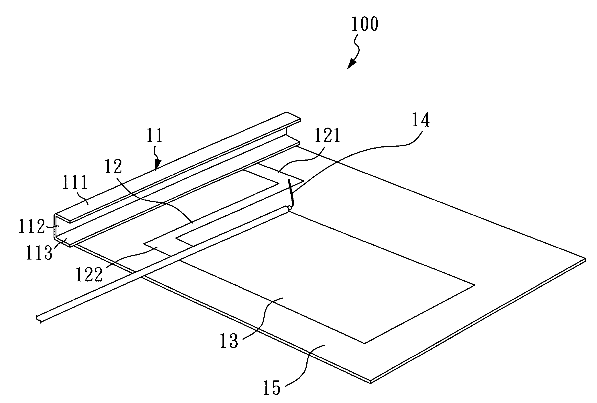
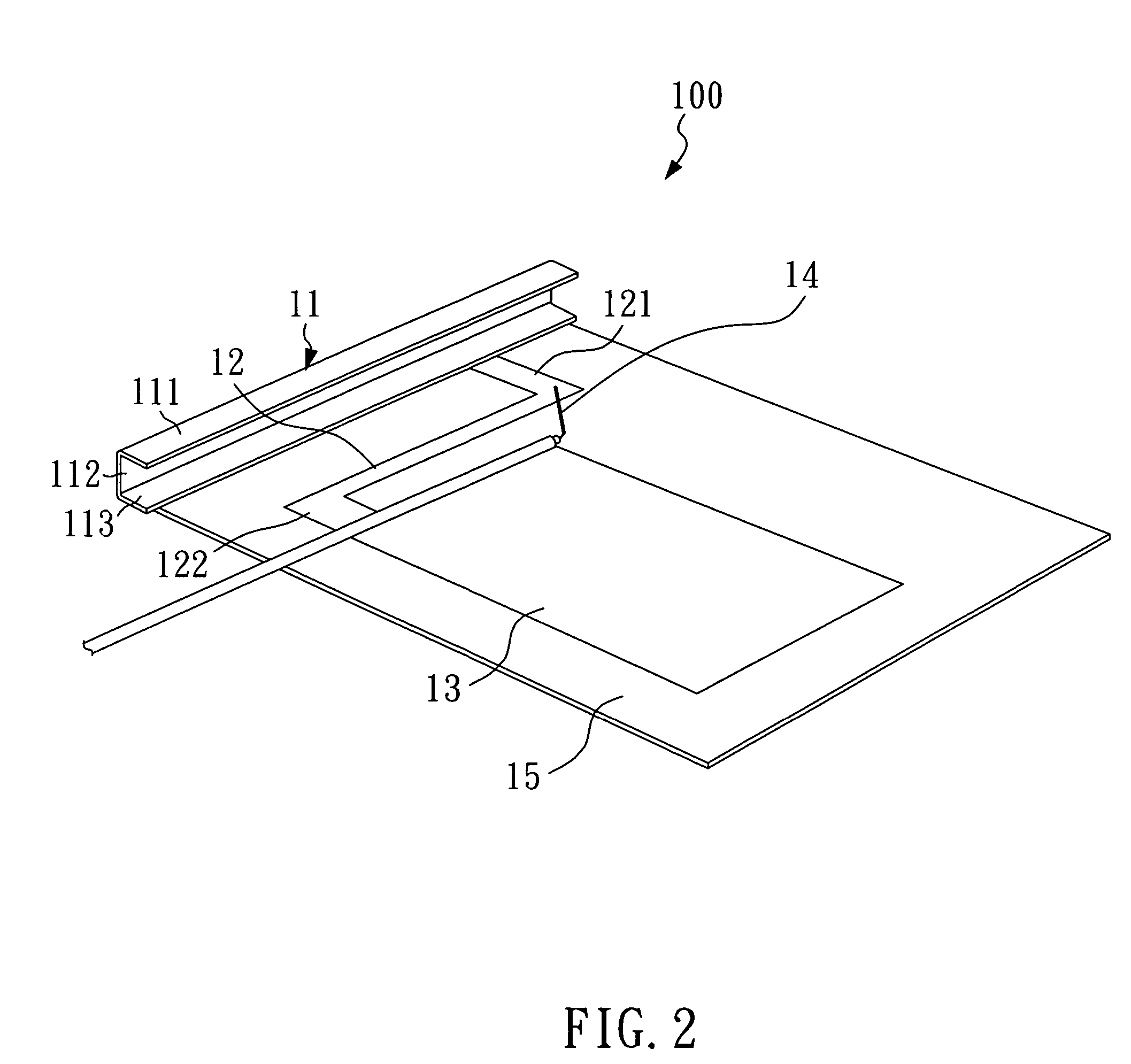
[0028]Please refer to FIG. 2. FIG. 2 is a schematic drawing of a broadband antenna according to a first embodiment of the present invention. As shown in the drawing, in the first embodiment, the broadband antenna 100 comprises a radiating element 11, a connecting element 12, a grounding element 13, a feed line 14 and a PCB (printed circuit board) 15.

[0029]The connecting element 12 has a first end 121 and a second end 122. The first end 121 is electrically connected between the two ends of the radiating element 11, which has a U-shaped structure, and the second end 122 is electrically connected to grounding element 13. The connecting element 12 and the grounding element 13 are both mounted on the PCB 15. One end of the feed line 14 is electrically connected to the first end 121 of the connecting element 12 and the other end of the feed line 14 is electrically connected to a radio receiving / transmitting device (not shown) to electrically connect the radiating element 11 to the radio r...


PUM


Abstract

A broadband antenna for wireless communication system, the broadband antenna includes a radiating element, a grounding element and a connecting element for connecting the radiating element and the grounding element. The radiating element has a U-shaped structure, a V-shaped structure or an L-shaped structure. The broadband antenna of the present invention has wider frequency bandwidth and higher antenna efficiency.

Description

BACKGROUND OF THE INVENTION[0001]1. Field of the Invention[0002]The present invention relates to an antenna, and more particularly, to a dual-band broadband antenna.[0003]2. Description of the Related Art[0004]With the developments in wireless communications technology, many electronic devices, such as notebooks and mobile phones, now incorporate wireless communications abilities. In order to receive and transmit signals, these electronic devices need to have an antenna for detecting electromagnetic wave.[0005]Since both mobile phones and notebooks have became important in the daily lives of many people, if it were possible to combine these two devices, such a combined-function device would offer significantly more convenience for users. However, the prior art antennas for typical mobile phones usually have a frequency bandwidth of about 70 MHz at a low frequency range (900 MHz), and a frequency bandwidth of about 120 MHz at a high frequency range (1800 MHz) when a VSWR (Voltage Sta...

Claims


Application Information

Patent Timeline
Patent Type & Authority Patents(United States)
IPC IPC(8): H01Q1/24H01Q1/38H01Q9/00H01Q9/36
CPCH01Q1/243H01Q1/38H01Q9/36
Inventor CHEN, CHIH LUNGLIU, CHIH KAI
Owner WISTRON NEWEB
Why Eureka
Try Eureka