Hoop antenna

a technology of hoop antenna and antenna body, which is applied in the direction of antenna earthing, resonant antenna, radiating element structural form, etc., can solve the problems of reducing the radiation efficiency, reducing the frequency bandwidth, and reducing the cost of manufacture, so as to achieve the effect of wide frequency bandwidth and less cost of manufactur

Inactive Publication Date: 2009-01-27
FLEXTRONICS AP LLC
View PDF15 Cites 8 Cited by
  • Summary
  • Abstract
  • Description
  • Claims
  • Application Information

AI Technical Summary

Benefits of technology

[0015]Advantageously, the hoop shape antenna of the present invention is capable of transmitting signals in both a radio and mobile network at a wide frequency bandwidth. Further, this hoop antenna is more efficient than conventional antennas with respect to battery usage. Also, the hoop shape, particularly when designed into the structure of a printed circuit board, is less costly to manufacture.

Problems solved by technology

Traditional antennas such as monopoles, dipoles and even patches are unable to meet these requirements and hence alternative approaches are needed.
The structure is mechanically sturdy, but the dielectric body block makes it relatively heavy.
Further, the dielectric body makes the impedance bandwidth of the antenna narrower and degrades the radiation efficiency as compared to an air-insulated PIFA structure.
However, these PIFA structures are not designed to fit in a small confined space while communicating efficiently in a wide frequency band.

Method used


Image

  • Hoop antenna
  • Hoop antenna
  • Hoop antenna

Examples


Embodiment Construction

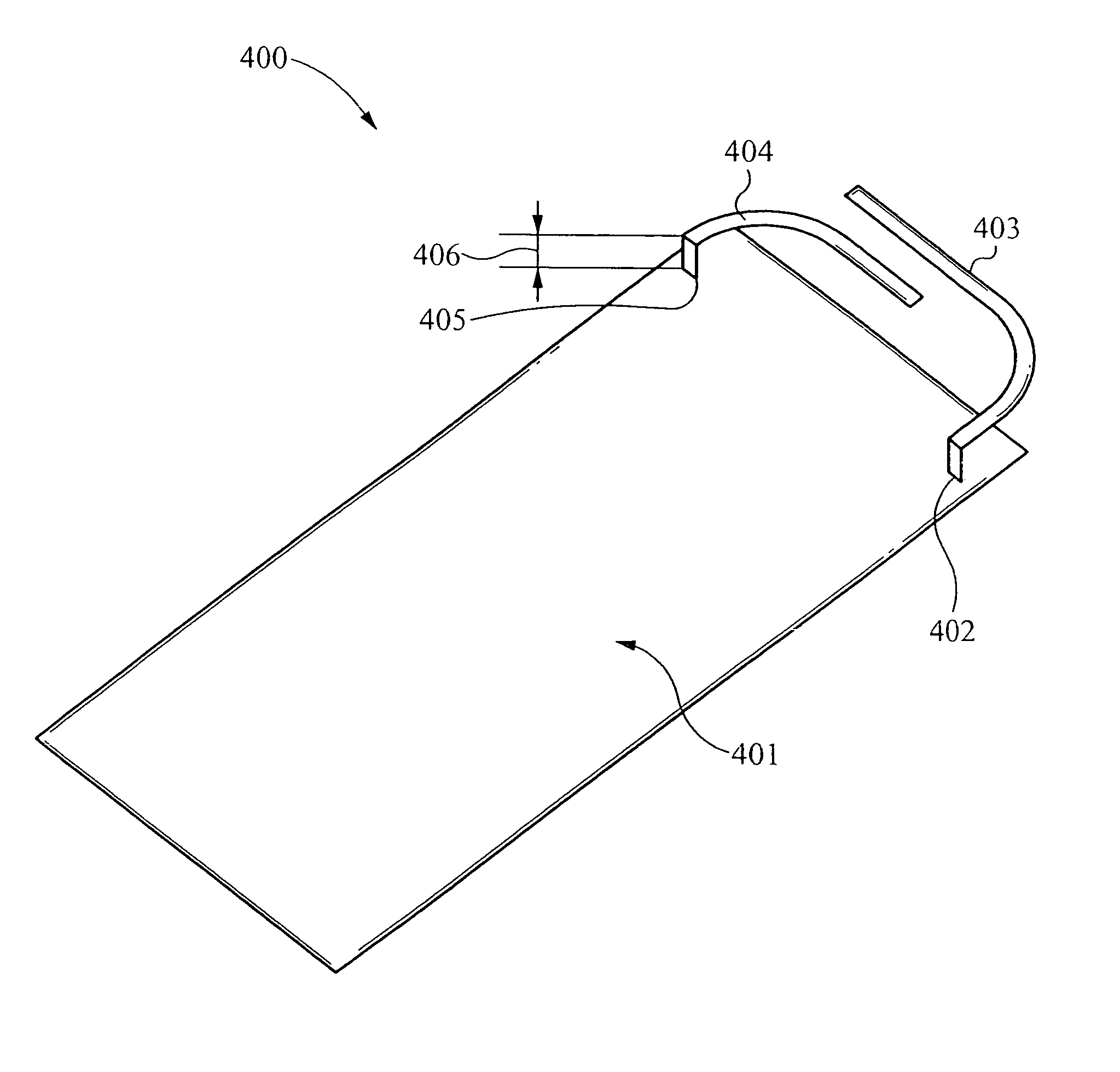
[0023]An invention for hoop shape antenna for use in a relatively small space, such as a mobile phone, is disclosed. Numerous specific details are set forth to provide a thorough understanding of the present invention. It will be understood, however, to one skilled in the art, that the present invention can be practiced with other specific details.

[0024]FIG. 4 is a drawing of a hoop antenna 400 for a mobile communication device, in accordance with the present invention. The hoop antenna 400 includes a ground plane 401. Examples of a ground plane include copper on FR4 laminate, a printed circuit board or other dielectric material. One end of a feeding arm 404 is electrically coupled to a feeding contact 405. The feeding contact 405 is electrically coupled to the ground plane 401. One end of a ground arm 403 is electrically coupled to a ground contact 402. The ground contact 402 is electrically coupled to the ground plane 401.

[0025]The feeding arm 404 is the antenna port for transmitt...


PUM


Abstract

An antenna for use in a relatively small confined space, such as a mobile phone, is provided. In one example, the antenna includes a feeding arm having an end coupled to a feeding contact; and a grounded arm having an end coupled to a ground contact, wherein the feeding arm and the grounded arm are bent to conform to the relatively small confined volume. The relatively small confined volume can be internal space of a mobile communication device. The mobile communication device can be a mobile phone, for example.

Description

BACKGROUND OF THE INVENTION[0001]1. Field of the Invention[0002]The present invention generally relates to relatively electrical small antennas. More particularly, the present invention relates to antenna structures for mobile communication devices having constraints on internal space and battery consumption.[0003]2. Discussion of Background[0004]There has been increasing need for innovative antennas on mobile terminals in wireless communications including the global system for mobile communications (GSM850) or extended GSM (EGSM), the digital communication system (DCS), the personal communication system (PCS), and wide-band code-division multiple access (WCDMA). Constraints on such antenna design include requirements of multiband or broadband resonance, limitation of space in handheld devices, reduction of radio absorption in the user's head or body for antenna efficiency and safety measures, and cost reduction. Traditional antennas such as monopoles, dipoles and even patches are u...

Claims


Application Information

Patent Timeline
Patent Type & Authority Patents(United States)
IPC IPC(8): H01Q1/24
CPCH01Q1/243H01Q7/00H01Q7/005
Inventor ROSENGREN, KENTRYLANDER, JOACIM
Owner FLEXTRONICS AP LLC
Why Eureka
Try Eureka