Eureka AIR delivers breakthrough ideas for toughest innovation challenges, trusted by R&D personnel around the world.

Multi-band antenna

a multi-band antenna and antenna technology, applied in the field of antennas, can solve the problems of large height of pifa antenna, insufficient space for installing such pifa antennas, and insatisfaction of electronic devices, and achieve the effect of wide frequency bandwidth and compact siz

Inactive Publication Date: 2010-04-27
HON HAI PRECISION IND CO LTD
View PDF10 Cites 7 Cited by
  • Summary
  • Abstract
  • Description
  • Claims
  • Application Information

AI Technical Summary

Benefits of technology

[0007]A primary object, therefore, of the present invention is to provide a multi-band antenna with wide frequency bandwidth and suitable to be installed in a notebook or other portable electrical devices with compact size.

Problems solved by technology

However, more and more people dissatisfy their electronic devices only working in an immovable network (Signal transmission distance is 10 meters in Bluetooth which almost doesn't permit the electronic devices to move.) or a only short-haul movable network (Signal transmission distance is 150 meters of 802.11 technical standard which limits the movement of the electronic device except between work rooms.) of the WLAN.
However, the PIFA antenna has relatively big size in height direction.
So, many notebooks or other portable electronic devices do not have enough space to install such PIFA antenna.

Method used


Image

  • Multi-band antenna
  • Multi-band antenna
  • Multi-band antenna

Examples


Embodiment Construction

[0014]Reference will now be made in detail to a preferred embodiment of the present invention.

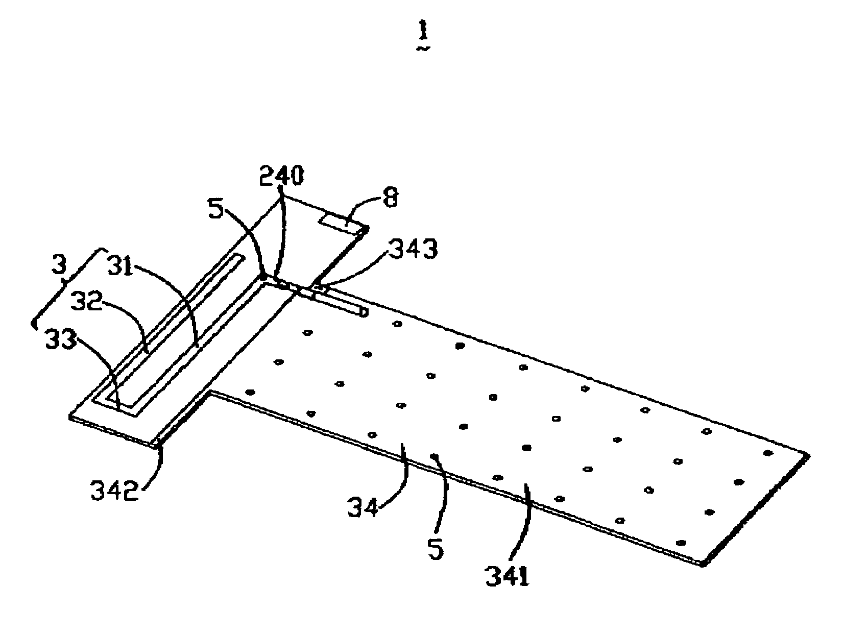
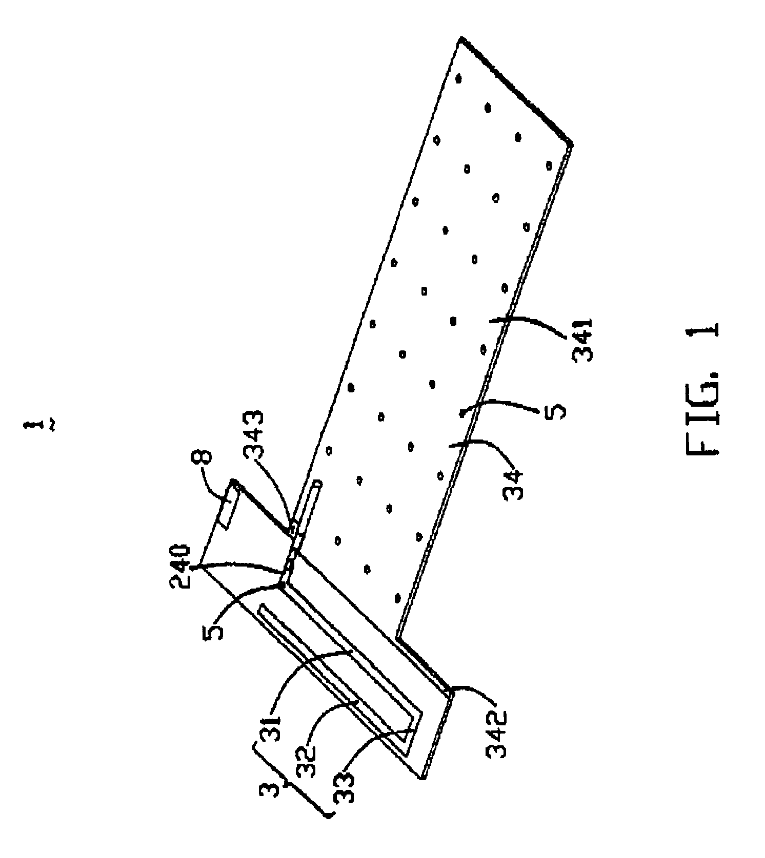
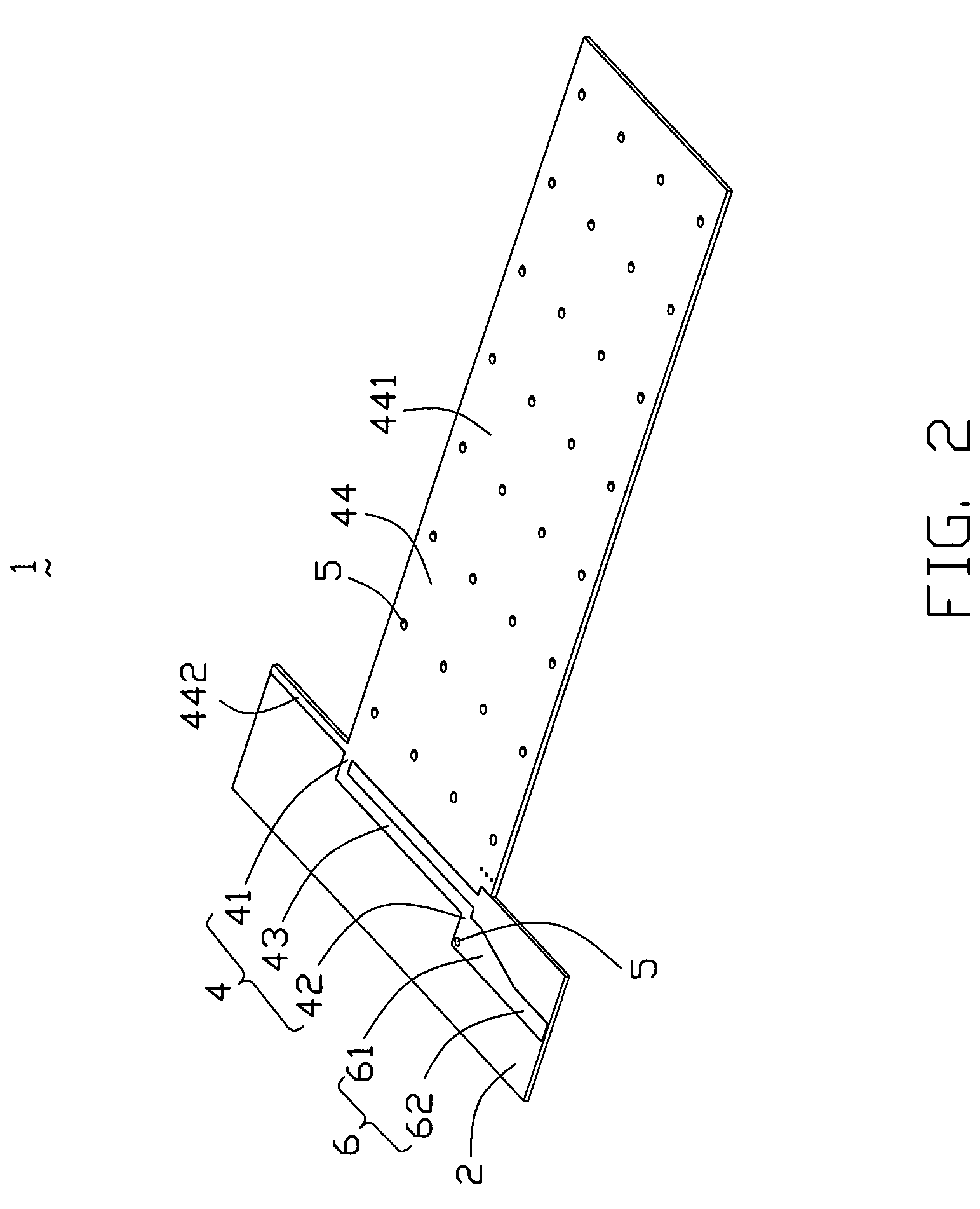
[0015]Referring to FIG. 1 to FIG. 2, a multi-band antenna 1 according to the present invention operates at WWAN (824-960 MHz and 1710-2170 MHz). The multi-band antenna 1 comprises a T-shape PCB (Printed Circuit Board, PCB) 2, a first antenna body (not labeled) formed on a first surface of the PCB 2, and a second antenna body (not labeled) formed on a second surface of the PCB 2.

[0016]The first antenna body is a monopole antenna and comprises a first radiating element 3 formed on the upper section of the first surface of the PCB 2, and a first grounding element 34 formed on the lower section of the first surface of the PCB 2 and apart from the first radiating element 3. The first radiating element 3 has an inverted U-shape working at lower frequency (824-960 MHz) and comprises a first radiating arm 31, a second radiating arm 32 parallel to the first radiating arm 31, and a third radiating ar...


PUM


Abstract

A multi-band antenna used in a portable electrical device can operate in WWAN. The multi-band antenna includes a PCB, a first antenna body, and a second antenna body. The PCB has a first surface and an opposite second surface and defines a through hole extending from the first surface to the second surface. The first antenna body is formed on the first surface of the PCB comprising a first radiating element and a first grounding element. The second antenna body is formed on the second surface of the PCB. The second antenna body comprises a second radiating element, a second grounding element, and a connecting element connecting the second radiating element and the second grounding element. The first radiating element and the second radiating element electrically connect with each other via the through hole of the PCB. A feeding line has an inner conductor electrically connecting to the first radiating element and an outer conductor electrically connecting to the first grounding element.

Description

BACKGROUND OF THE INVENTION[0001]1. Field of the Invention[0002]The present invention relates generally to an antenna, and more particularly to a multi-band antenna comprising a PIFA (Planar Inverted-F Antenna) and a monopole antenna.[0003]2. Description of the Prior Art[0004]With the development of wireless communication, more and more portable electronic devices, such as notebooks, install antenna systems for working in a Wireless Local-area Network (WLAN). Transmitting and receiving signals plays an important role in wireless communication process. In recent years, a majority of WLAN bases on Bluetooth technical standard or 802.11 technical standard. Antenna in Bluetooth technical standard is based on 2.4 GHz frequency band, and in 802.11 technical standard is based on 2.4 GHz and 5 GHz. So, an antenna in a notebook mostly works at the above frequency bands at the present time.[0005]However, more and more people dissatisfy their electronic devices only working in an immovable net...

Claims


Application Information

Patent Timeline
Patent Type & Authority Patents(United States)
IPC IPC(8): H01Q1/24H01Q5/10
CPCH01Q1/2266H01Q1/243H01Q21/28H01Q9/42H01Q9/0421
Inventor HUNG, CHEN-TACHEN, SHANG-JENTSENG, HSIEN-SHENG
Owner HON HAI PRECISION IND CO LTD
Why Eureka
Eureka Blog
Learn More