Antenna apparatus

a planar antenna and antenna technology, applied in loop antennas, non-resonant long antennas, rhombic antennas, etc., can solve the problems of degrading transmission quality and ignoring road reflection, and achieve the effect of high gain

Inactive Publication Date: 2009-03-17
PANASONIC CORP
View PDF9 Cites 1 Cited by
  • Summary
  • Abstract
  • Description
  • Claims
  • Application Information

AI Technical Summary

Benefits of technology

[0016]As described above, an antenna apparatus of the present invention can achieve high gain and switch the main beam in two directions with a small, planar configuration. In addition, it is possible to switch the angle of the main beam in the horizontal direction.

Problems solved by technology

In these communication systems, since the antenna apparatus installed in a vehicle is positioned comparatively close to the road (inside a bumper, for example), there is a problem that reflection from the road cannot be ignored and transmission quality degrades due to fading.

Method used


Image

  • Antenna apparatus
  • Antenna apparatus
  • Antenna apparatus

Examples


embodiment 1

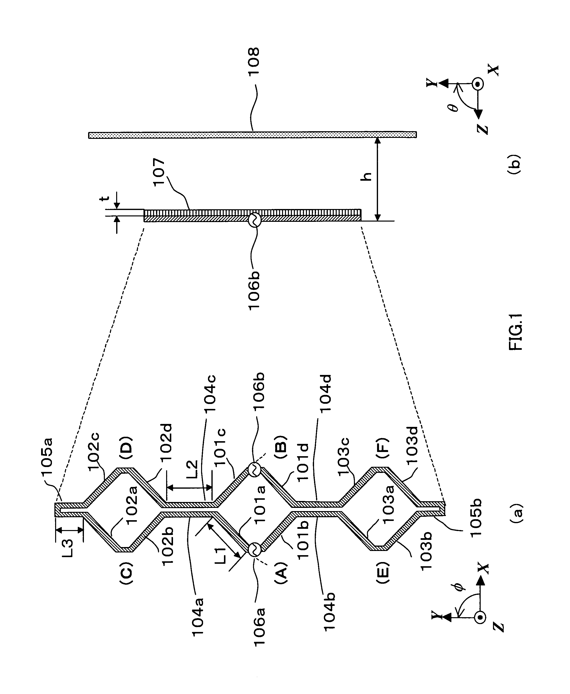
[0039]FIG. 1 is a drawing showing the configuration of an antenna apparatus according to Embodiment 1 of the present invention. Below, a case will be described in which an antenna is created on a dielectric substrate of, for example, εr=2.26, assuming that its operating frequency is 25 GHz and one wavelength (one effective wavelength) is 8.6 mm. The coordinate axes shown in FIG. 1 are defined for convenience of explanation.

[0040]FIG. 1(a) is a planar view showing the configuration of an antenna apparatus according to Embodiment 1 of the present invention. In this figure, linear elements 101a through 101d, 102a through 102d, and 103a through 103d are electrical conductors with element length L1 of approximately ⅓ wavelength (2.8 mm), and an element width of, for example, 0.2 mm. These linear elements 101a through 101d, 102a through 102d, and 103a through 103d are arranged in square shapes as shown in FIG. 1(a).

[0041]Linear linking elements 104a through 104d are electrical conductors ...

embodiment 2

[0060]FIG. 5 is a drawing showing the configuration of an antenna apparatus according to Embodiment 2 of the present invention. FIG. 5(a) is a planar view showing the configuration of the antenna apparatus, and FIG. 5(b) is an arrow view showing the configuration of the antenna apparatus viewed from the +X side of FIG. 5(a). In these figures, parts common to FIG. 1 are assigned the same reference numerals as in FIG. 1 without further explanations. Below, a case will be described in which an antenna is created on a dielectric substrate of, for example, εr=2.26, assuming that its operating frequency is 25 GHz and one wavelength (one effective wavelength) is 8.6 mm. The coordinate axes shown in the figures are defined for convenience of explanation.

[0061]Feed point 501a is provided between linear elements 102a and 102b, and feed point 501b is provided between linear elements 102c and 102d. Linear elements 101a and 101b, linear elements 101c and 101d, linear elements 103a and 103b, and ...

embodiment 3

[0072]FIG. 9 is a drawing showing the configuration of an antenna apparatus according to Embodiment 3 of the present invention. FIG. 9(a) is a planar view showing the configuration of the antenna apparatus, in which feed points 901a, 901b, 902a, 902b, 903a and 903b are provided at the peaks opposite to the respective rhombic antenna sections, and the feed points are switched. FIG. 9(b) is an arrow view showing the configuration of the antenna apparatus viewed from the +X side of FIG. 9(a). In these figures, parts common to FIG. 1 are assigned the same reference numerals as in FIG. 1 without further explanations. Below, a case will be described in which an antenna is created on a dielectric substrate of, for example, εr=2.26, assuming that its operating frequency is 25 GHz and one wavelength (one effective wavelength) is 8.6 mm. The coordinate axes shown in the figures are defined for convenience of explanation.

[0073]An example of feed point switching according to an antenna apparatu...


PUM


Abstract

An antenna apparatus capable of main beam direction switching is provided that achieves high gain with a small, planar configuration. Rhombic antenna sections composed of linear elements 101a through 101d, 102a through 102d, and 103a through 103d are arranged in the same plane, and the rhombic antenna sections are connected by linear linking elements 104a through 104d. Linear detour elements 105a and 105b are connected to the pair of vertices of the rhombic antenna sections arranged at each end. Feed points 106a and 106b are provided at the other opposite two pairs of vertices of any of the rhombic antenna sections, and the opposite vertices of the other rhombic antenna sections are connected by linear elements. A plate reflector is arranged at a distance h from, and parallel to, the surface on which the rhombic antenna elements are arranged.

Description

[0001]This application is a national stage application of PCT application number PCT / JP2005 / 021802, filed on Nov. 28, 2005.TECHNICAL FIELD[0002]The present invention relates to a small planar antenna apparatus capable of main beam direction switching, and is suitable for use as a high speed radio communication antenna in, for example, road-to-vehicle communication or vehicle-to-vehicle communication.BACKGROUND ART[0003]In recent years, road-to-vehicle communication systems and vehicle-to-vehicle communication systems using 25 GHz band, 60 GHz band, and so forth, have been studied. In these communication systems, since the antenna apparatus installed in a vehicle is positioned comparatively close to the road (inside a bumper, for example), there is a problem that reflection from the road cannot be ignored and transmission quality degrades due to fading. Therefore, the antenna apparatus installed in a vehicle needs to have narrow directivity to the vertical direction with respect to t...

Claims


Application Information

Patent Timeline
Patent Type & Authority Patents(United States)
IPC IPC(8): H01Q13/10
CPCH01Q1/32H01Q3/247H01Q7/00H01Q11/06H01Q13/10
Inventor NAKANISHI, TOMOYAUNO, HIROYUKISAITO, YUTAKA
Owner PANASONIC CORP
Why Eureka
Try Eureka