Interferometric apparatus for producing an output signal characteristic of phase and/or amplitude noise of a device

a technology of interferometry and output signal, which is applied in the direction of noise figure or signal-to-noise ratio measurement, measurement devices, instruments, etc., can solve the problems that the sensitivity of this method is the noise of the mixer itself, and the noise of the mixer, including dc voltage drift, still influences the baseband signal

Active Publication Date: 2009-03-17
RAYTHEON CO
View PDF3 Cites 3 Cited by
  • Summary
  • Abstract
  • Description
  • Claims
  • Application Information

AI Technical Summary

Problems solved by technology

A limitation of the sensitivity of this method is the noise of the mixer itself, which can dominate the baseband signal if the device is sufficiently low noise.
However, the mixer's noise, including DC voltage drift, still influences the baseband signal, albeit at a far lower level, and typically only at small frequency offsets from the microwave signal.

Method used


Image

  • Interferometric apparatus for producing an output signal characteristic of phase and/or amplitude noise of a device
  • Interferometric apparatus for producing an output signal characteristic of phase and/or amplitude noise of a device
  • Interferometric apparatus for producing an output signal characteristic of phase and/or amplitude noise of a device

Examples


first embodiment

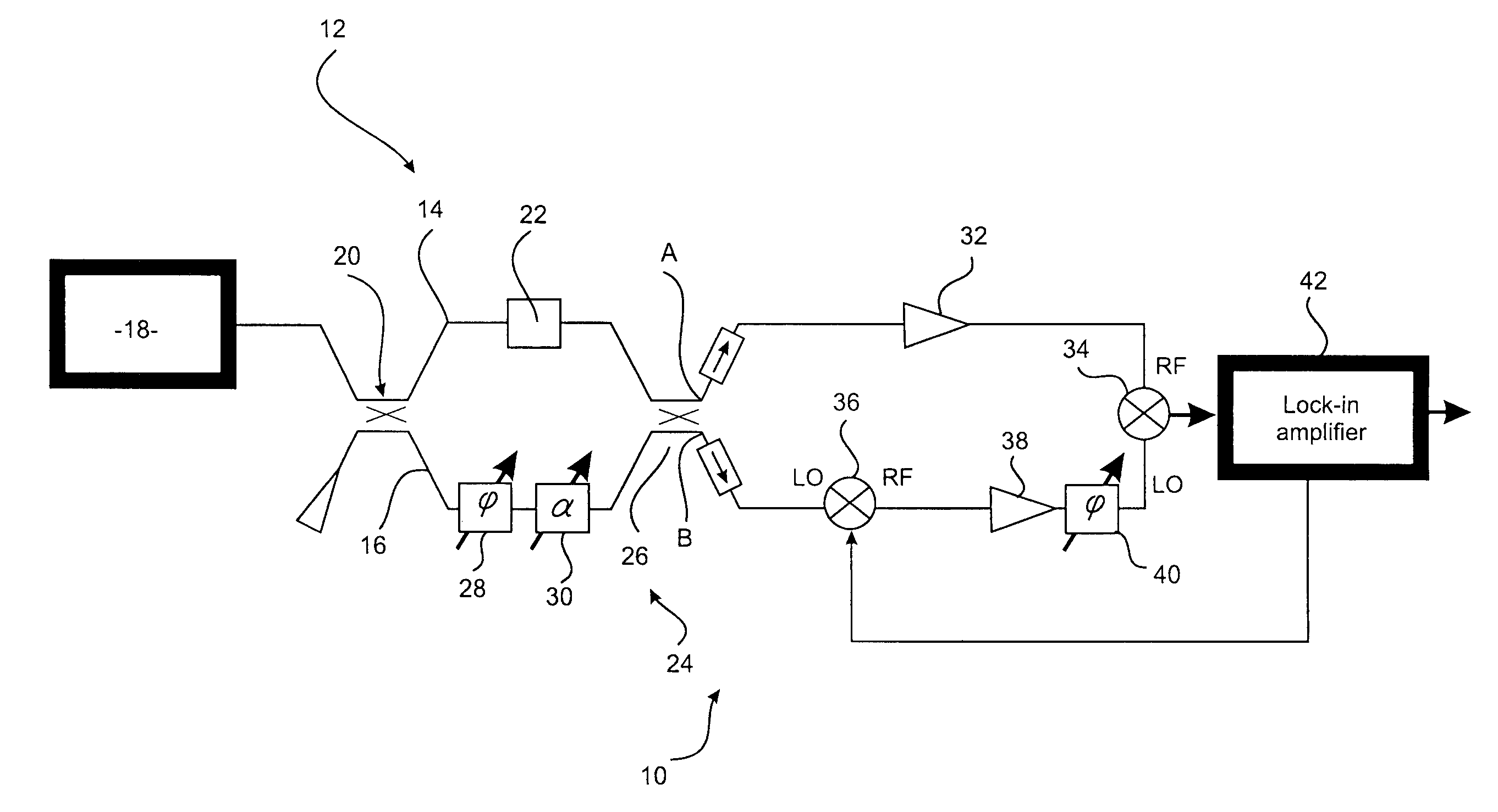
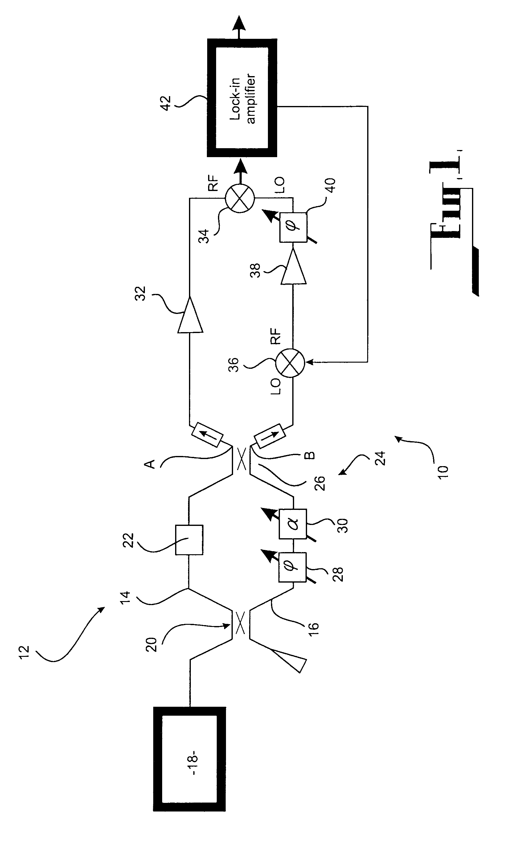
[0034]Shown in FIG. 1 is an interferometric apparatus 10 comprising a first bridge 12 having first and second arms 14 and 16. A signal generator 18 provides an input signal that becomes a first signal and a second signal input to the first and second arms 14 and 16, respectively, via a power splitter 20.

[0035]A device under test 22 is provided in the first arm 14 of the first bridge 12.

[0036]A carrier suppression means 24 is provided, in the form of a power combiner 26, phase shifter 28 and attenuator 30. The phase shifter 28 and the attenuator 30 are provided in the second arm 16 of the first bridge 12. The power combiner 26 is connected to the first and second arms 14 and 16. The phase shifter 28, attenuator 30 and power combiner 26 are arranged to produce a carrier-suppressed signal at an output A of the power combiner 26 and to produce a carrier-dominated signal at an output B of the power combiner 26, as described in the references incorporated herein.

[0037]A first amplifier 3...

second embodiment

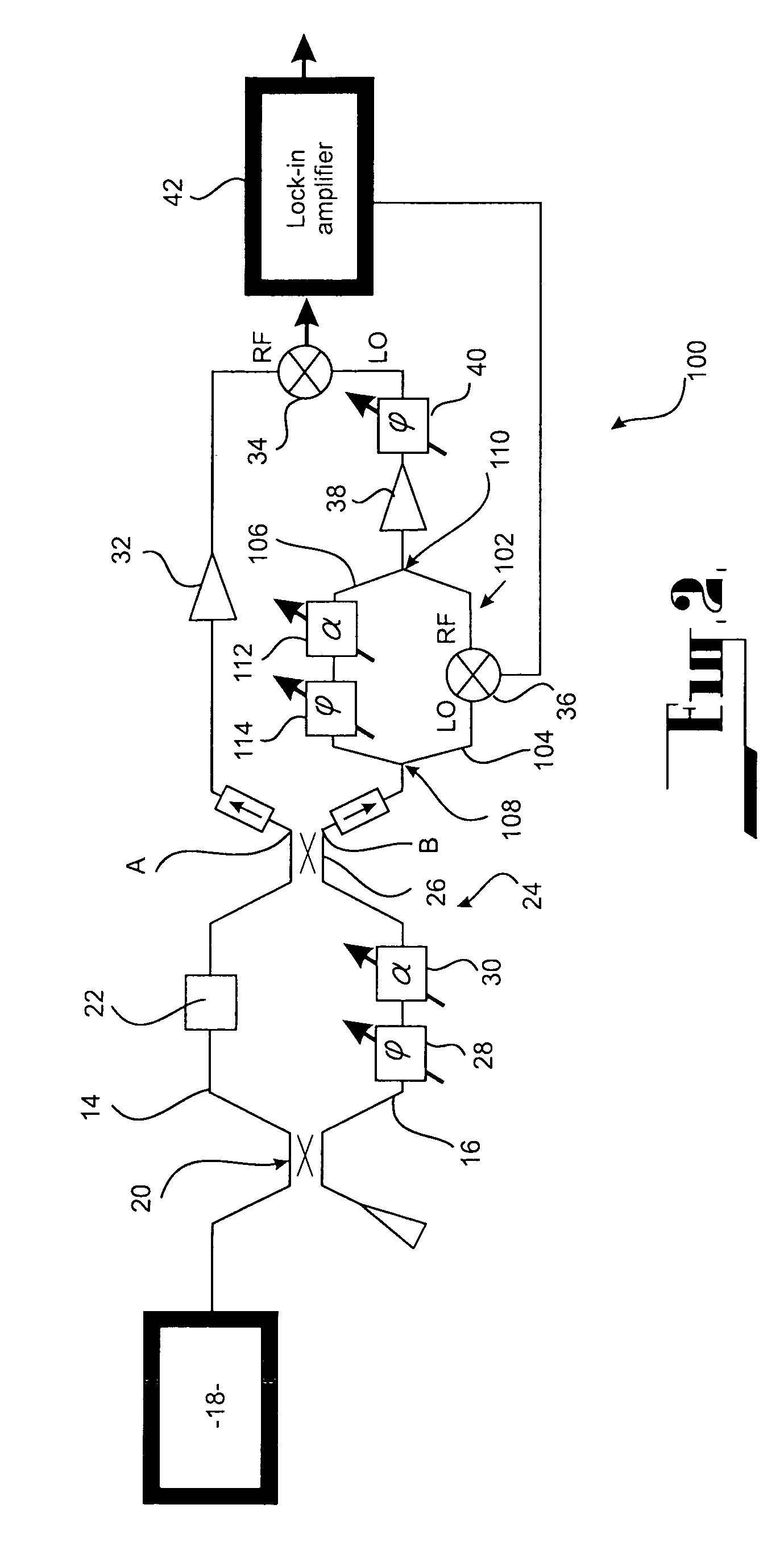
[0054]The interferometric apparatus 200 is similar to the apparatus 100 of the second embodiment, except that a signal combination means formed by the second bridge 102, comprising the second mixer 36 therein, and second amplifier 38 is provided between the signal generator 18 and the first bridge 12, and also that a frequency divider 202 is provided between the lock-in amplifier 42 and the second mixer 36. In this embodiment, the fourth signal is the input signal from the signal generator 18.

[0055]By placing the signal combination means at the input to the first bridge 12, the third signal, output from the amplifier 38, drives the first bridge 12. The frequency divider 202 is placed between the lock-in amplifier 42 and the second mixer 36 so that the signal produced by the first mixer 34 is still at carrier frequency foffset.

[0056]FIG. 4 shows the improvement in the phase noise floor achieved using the interferometric apparatus 100 (curve “2”) compared to prior art interferometric ...


PUM

PropertyMeasurementUnit
fourier offset frequenciesaaaaaaaaaa
fourier offset frequencyaaaaaaaaaa
phaseaaaaaaaaaa

Abstract

An interferometric apparatus (10) for producing an output signal characteristic of phase and / or amplitude noise of a device under test (22), an input signal being provided to the interferometric apparatus (10), comprising a signal generation means (36,38) arranged to produce a third signal having a carrier frequency offset from that of the input signal; a first bridge (12) having first (14) and second (16) arms, the first (14) and second (16) arms having input thereto first and second signals, respectively, produced from one of the input signal or the third signal; the device under test (22) being provided in one of the first (14) or second (16) arms of the first bridge (12); a carrier suppression means (24) connected to the first (14) and second (16) arms of the first bridge (12) to produce a carrier suppressed signal; a first amplifier (32) arranged to amplify the carrier suppressed signal; first mixing means (34) responsive to the third signal and to the carrier suppressed signal to produce a signal characteristic of phase and / or amplitude noise of the device under test (22) at an offset frequency.

Description

FIELD OF THE INVENTION[0001]This invention relates to an interferometric apparatus for measuring the phase and / or amplitude noise of a device at microwave frequencies.[0002]Throughout the specification, unless the context requires otherwise, the word “comprise” or variations such as “comprises” or “comprising”, will be understood to imply the inclusion of a stated integer or group of integers but not the exclusion of any other integer or group of integers.BACKGROUND ART[0003]One technique used to measure the phase and / or amplitude noise of a device at microwave frequencies is to interrogate the device using a reference signal. The device adds amplitude and / or phase noise to the reference signal to produce a modified signal. The modified signal is then compared to the reference signal using a double-balanced mixer, which produces a baseband signal representative of the phase or amplitude noise of the device, according to the relative phase between the reference signal and the modifie...

Claims


Application Information

Patent Timeline
Patent Type & Authority Patents(United States)
IPC IPC(8): G01B9/02G01N21/00
CPCG01R29/26
Inventor IVANOV, EUGENE NIKOLAYFOWLER, ALISON CLARETOBAR, MICHAEL EDMUND
Owner RAYTHEON CO
Why Eureka
Try Eureka