Transmitting and receiving apparatus for supporting transmit antenna diversity using space-time block code

a technology of space-time block code and transmit antenna, applied in diversity/multi-antenna system, modulation, electromagnetic wave modulation, etc., can solve the problem that the decoding complexity increases exponentially with the transmission rate, and the transmitter is almost impossible to have perfect instantaneous information about the characteristics of the receiver, etc. problem, to achieve the effect of maximum diversity gain and maximum transmission ra

Active Publication Date: 2009-03-17
SAMSUNG ELECTRONICS CO LTD
View PDF6 Cites 39 Cited by
  • Summary
  • Abstract
  • Description
  • Claims
  • Application Information

AI Technical Summary

Benefits of technology

[0030]It is, therefore, an object of the present invention to provide a transmit diversity apparatus that provides a maximum transmission rate and a maximum diversity gain in a communication system using 3 or more transmit antennas.
[0031]It is another object of the present invention to provide a transmit diversity apparatus that provides a maximum diversity gain with a very simple encoding and decoding structure in a communication system having using 3 or more transmit antennas.
[0032]It is a further object of the present invention to provide a transmit diversity apparatus that provides a maximum diversity gain in a communication system transmitting complex symbols through 3 or more transmit antennas.

Problems solved by technology

In practice, however, it is nearly impossible for the transmitter to have perfect instantaneous information about the characteristics of the receiver because of mobility and channel changes.
Also, the use of feedback channels for reporting channel status information to the transmitter may not be desirable since it reduces channel capacity.
However, according to the above space-time coding techniques, the decoding complexity increases exponentially with transmission rate when the number of transmit antennas is fixed.
Therefore, they are not feasible for a large of transmit antennas and at a high bandwidth efficiency.
Despite the advantage of simple transmission / reception, these codes cannot achieve all possible diversity gains without data rate losses when complex symbols are transmitted through 3 or more antennas, due to the orthogonality condition for the columns of a transmission matrix.
This problem makes them less attractive for real wireless applications.

Method used


Image

  • Transmitting and receiving apparatus for supporting transmit antenna diversity using space-time block code
  • Transmitting and receiving apparatus for supporting transmit antenna diversity using space-time block code
  • Transmitting and receiving apparatus for supporting transmit antenna diversity using space-time block code

Examples


first embodiment

Decoding

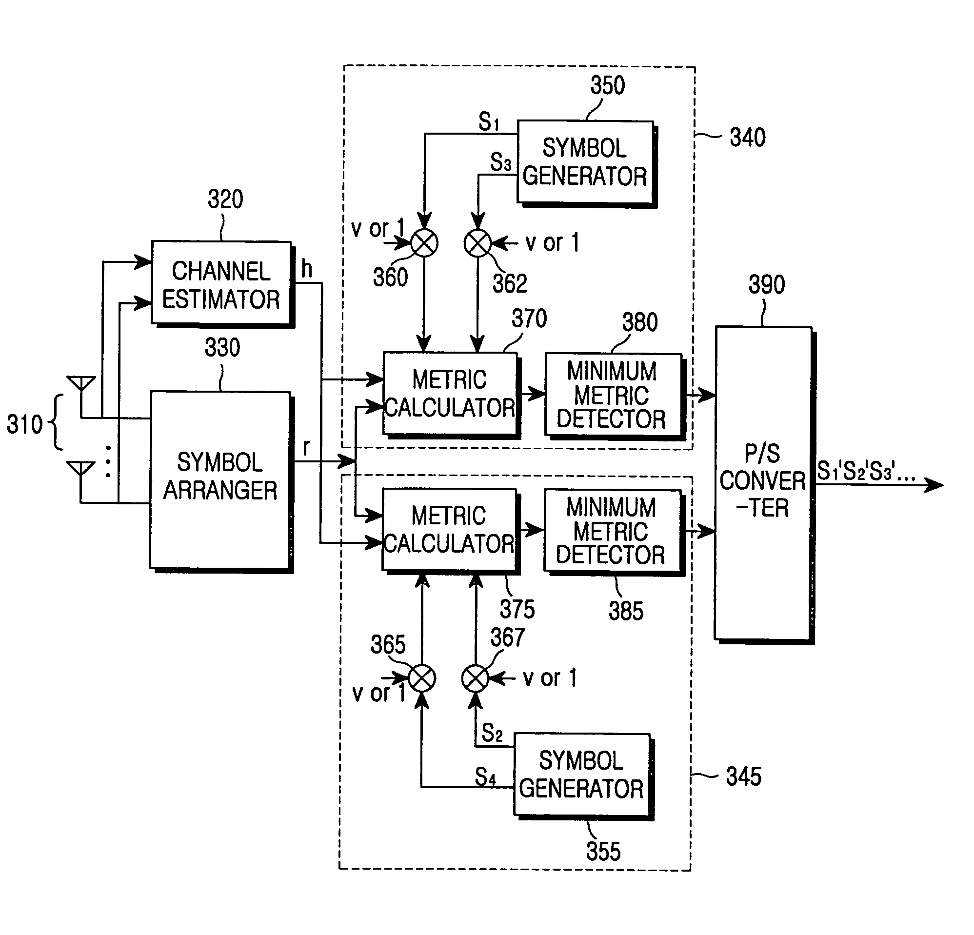
[0094]FIG. 5 is a block diagram of a receiver that decodes according to an embodiment of the present invention. The receiver is comprised of two independent decoders 340 and 345.

[0095]Referring to FIG. 5, a channel estimator 320 estimates channel coefficients representing channel gains from a plurality of transmit antennas to a plurality of receive antennas 310. A symbol arranger 330 collects symbols received from the receive antennas 310 for the four time periods corresponding to transmission by the transmitter illustrated in FIG. 3 or FIG. 4 of one block of symbols at four times.

[0096]The symbol arranger 330 forms a matrix out of the collected symbols. In the matrix, symbols received from the same receive antenna are arranged in the same row and symbols received at the same time are arranged in the same column. Although the plurality of receive antennas 310 are illustrated, decoding for the case of one antenna will be described below, for notational simplicity.

[0097]If fou...

second embodiment

Decoding

[0127]For ML decoding according to the first embodiment, the metric values of all possible symbol pairs must be computed to detect desired symbols. Thus, 8×8 metric calculations are required for 8PSK, and 16×16 metric calculations for 16QAM. These codes can be decoded very quickly by reducing the number of required computations utilizing the characteristics of PSK and QAM.

[0128]FIGS. 6A, 6B and 6C illustrate BPSK, QPSK, and 8PSK signal constellations, respectively. As shown, all PSK modulation symbols lie on a unit circle, which implies that their length is always 1.

[0129]For U6, since x1 and x3 both have length 1, as shown in equation (42), minimizing the metric (35) is equivalent to minimizing

|R1−x1|2+|R3−x3|2+|x1R13−x3|2  (42)

[0130]For each fixed x1, as shown in equation (43), minimizing the sum of equation (42) is equivalent to minimizing

|(R3+x1R13)−x3|2  (43)

[0131]Since x1 is fixed, minimizing the metric of equation (43) is equivalent to finding the closest constellatio...

third embodiment

Decoding

[0147]QPSK or 8PSK symbols can be decoded with a reduced volume of computations despite a lower symbol detection performance, as compared to decoding methods according to the first and second embodiments.

[0148]For 8PSK symbols, the receiver computes the parameters R1, R3 and R13 and finds the closest constellation points q1 to R1, q3 to R3, and q13 to R13. If q13=q1*q3, the receiver outputs q1 and q3.

[0149]If not, the receiver computes an angle Φd by dividing the angle between ql3 and q1*q3 by 2. Then the receiver searches for desired first and second symbols by calculating the ML decoding metric values of first symbol and second symbol candidates whose angles are respectively within the angular distance Φd from q1 and q3.

[0150]Similarly, the receiver computes the parameters R2, R4 and R24 and finds the closest constellation points q2 to R2, q4 to R4, and q24 to R24. If q24=q2*q4, the receiver outputs q2 and q4.

[0151]If not, the receiver computes an angle Φd′ by dividing the...


PUM


Abstract

A transmitter and a receiver are disclosed herein that support transmit antenna diversity using space-time block coding in a wireless communication system. The transmitter produces symbol combinations containing, as their elements, input symbols, the inversions and conjugates of the symbols, and symbols obtained by rotating the phases of the symbols once, forms a matrix having symbols in at least two columns orthogonal to each other with the symbol combinations, and transmits the matrix. The receiver detects symbols that minimize maximum likelihood (ML) decoding metrics over all possible symbols using channel gains from transmit antennas to a receive antenna. Also, the receiver selects candidate symbols among all possible symbols according to the characteristics of transmitted modulation symbols and detects symbols that minimize the ML decoding metrics.

Description

PRIORITY[0001]This application claims priority under 35 U.S.C. § 120 to an application entitled “Full Rate Space-Time Block Codes For Complex Constellations” filed in the U.S. Patent and Trademark Office on Oct. 10, 2002 and assigned Ser. No. 60 / 417,466, the contents of which are incorporated herein by reference. This application claims priority under 35 U.S.C. § 119 to an application entitled “Transmitting and Receiving Apparatus for Supporting Transmit Antenna Diversity Using Space-Time Block Code” filed in the Korean Intellectual Property Office on Apr. 4, 2003 and assigned Ser. No. 2003-21364, the contents of which are incorporated herein by reference.BACKGROUND OF THE INVENTION[0002]1. Field of the Invention[0003]The present invention relates generally to a wireless communication system, and in particular, to a transmitting and receiving apparatus using transmit antenna diversity to combat the degradation effects of fading.[0004]2. Description of the Related Art[0005]One of eff...

Claims


Application Information

Patent Timeline
Patent Type & Authority Patents(United States)
IPC IPC(8): H04B7/02H04B7/06H04B7/08H04L1/06
CPCH04B7/0669H04B7/0697H04L1/0618H04L1/0643H04B7/0891H04B7/02
Inventor HWANG, CHAN-SOOTAROKH, VAHIDNAM, SEUNG-HOONCHUNG, JAE-HAKKIM, YUNG-SOO
Owner SAMSUNG ELECTRONICS CO LTD
Why Eureka
Try Eureka