Approach for routing an integrated circuit

a technology of integrated circuits and routing lines, applied in the field of integrated circuit routing lines, can solve the problems of inability to use manual methods, and inability to meet the needs of large integrated circuits containing millions of transistors

Inactive Publication Date: 2009-03-17
CHAPMAN DAVID C
View PDF8 Cites 32 Cited by
  • Summary
  • Abstract
  • Description
  • Claims
  • Application Information

AI Technical Summary

Problems solved by technology

Although manual routing can provide relatively compact designs, the manual approach is impractical for large integrated circuits containing millions of transistors.
However, the new wires usually have to be bent to avoid obstacles, i.e., devices and cells, in the layout.
However, the channel routing approach is not without its disadvantages.
Specifically, the channel routing approach becomes impractical or impossible if there are significant numbers of obstacles extending into the channel, or if pins and / or obstacles are in the middle of the routing area, or if there are pin connections on all four sides of the region to be routed (which greatly increases the difficulty of assigning tracks for spines).
As a result, area routers are generally more powerful than their channel router counterparts, but they tend to require substantially more computational resources to operate and are more difficult to implement.
For large integrated circuits, area routers can be impractical.
As a result, a routing grid based upon wires having contacts can waste a significant amount of space.
Completing one wire may well block another.
This may lead to still more blockages, requiring further rerouting.
In the worst case the area router might not be able to find a feasible solution for all wires.
It is noteworthy that these enhancements are restricted to orthogonal routing and mostly require the use of a coarse routing grid.
Unroutes are typically short sections of connecting wires that could not be completed with a channel router due to underestimation of resource requirements.
A significant limitation with conventional routing approaches, including both the channel routing approach and the area routing approach, is the inability to modify the geometry around a wire being defined.
Another reason is that most conventional routing approaches use only orthogonal geometry for wires and geometry changes such as clipping the corner of an enclosure do not provide a benefit unless the wire passing it is non-orthogonal.
A third reason is that non-orthogonal wires do not efficiently fit onto a coarse routing grid, requiring either a wasteful grid size or a “gridless” router.
Although some gridless routers have been designed, none of them are capable of routing non-orthogonal wires.

Method used


Image

  • Approach for routing an integrated circuit
  • Approach for routing an integrated circuit
  • Approach for routing an integrated circuit

Examples


Embodiment Construction

[0062]In the following description, for the purposes of explanation, specific details are set forth in order to provide a thorough understanding of the invention. However, it will be apparent that the invention may be practiced without these specific details. In other instances, well-known structures and devices are depicted in block diagram form in order to avoid unnecessarily obscuring the invention.

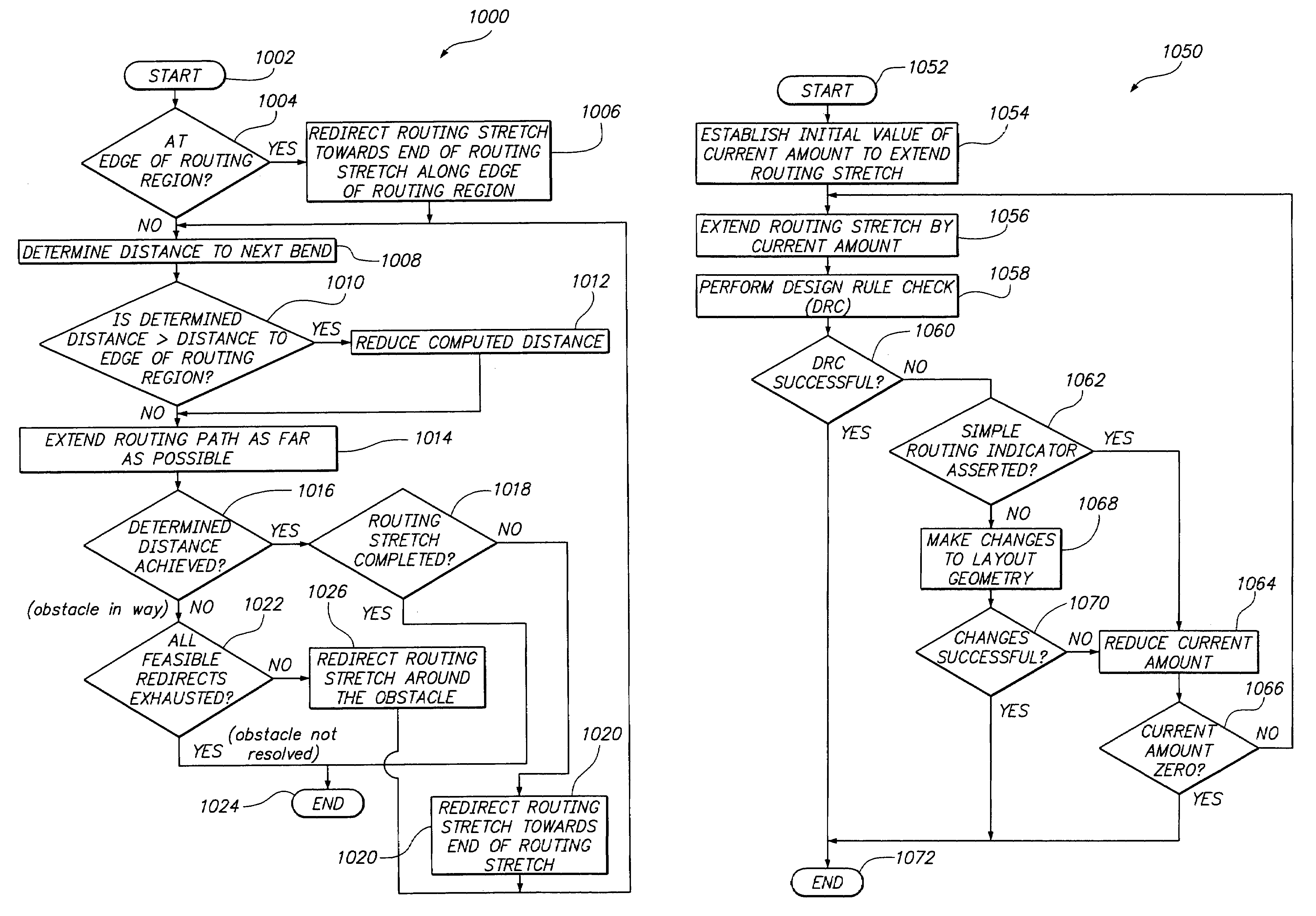
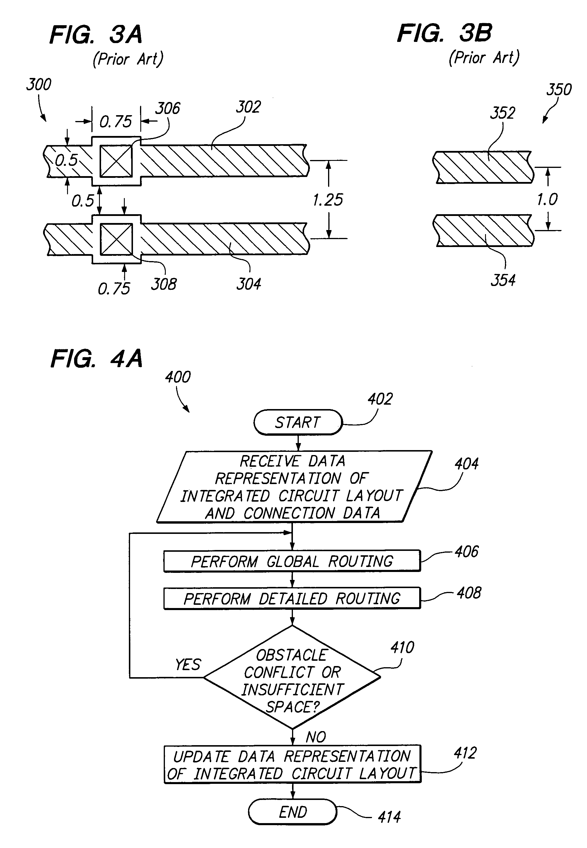
[0063]Various aspects and features of example embodiments of the invention are described in more detail hereinafter in the following sections: (1) introduction; (2) functional overview; (3) applicable principals; (4) global routing; (5) detailed routing; (6) obstacle and insufficient space resolution; and (7) implementation mechanisms.

1. Introduction

[0064]A computer-implemented approach for routing an integrated circuit using non-orthogonal routing is described. The approach is applicable to both intra-cell and inter-cell applications and can be adapted for use with orthogonal routing ...


PUM


Abstract

A computer-implemented approach for routing an integrated circuit using non-orthogonal routing is accomplished during two phases: a global routing phase and a detailed routing phase. During global routing, routing indicators, in the form of hint polygons, are added to the integrated circuit layout and strategy lists, that include bias directions and straying limits, are generated for the new wires to be added. The hint polygons and strategy lists are used during detailed routing to aid in placing the new wires. If obstacle conflicts or insufficient space problems prevent the detailed routing of a new wire, then an obstacle resolution portion of global routing is used to resolve the obstacle conflict and / or provide additional space in the integrated circuit layout to route the new wires. Obstacle resolution includes, without limitation, moving or changing layout geometry, changing or add hint polygons, changing the routing strategy by changing the bias direction and / or adjusting straying limits, inserting one or more layer changes, instructing the detailed router to backup and insert a bend, ripping-up and rerouting one or more wires, or routing the wire from the destination connection point. Also, a tight routing approach may be employed to accommodate constructing routing paths in tight layout areas. Object specific design rule checks are employed to increase routing flexibility optimize routing performance. “On-the-fly” design rule checks are performed on portions of routing paths as the routing paths are being constructed.

Description

RELATED APPLICATIONS AND CLAIM OF PRIORITY[0001]This application is a continuation of and claims priority to U.S. patent application Ser. No. 09 / 421,437 (now U.S. Pat. No. 7,065,729) filed on Oct. 19, 1999, entitled “APPROACH FOR ROUTING AN INTEGRATED CIRCUIT” and further claims priority to U.S. Provisional Application Ser. No. 60 / 104,872 filed on Oct. 19, 1998, entitled “ROUTING OF VLSI LAYOUTS.”, and U.S. Provisional Application Ser. No. 60 / 139,532 filed on Jun. 16, 1999, entitled “ROUTING OF VLSI LAYOUTS PLUS”, the contents of which are all hereby incorporated by reference in their entirety for all purposes as if fully set forth herein.FIELD OF THE INVENTION[0002]The present invention relates to integrated circuits, and more specifically, to an approach for routing an integrated circuit.BACKGROUND OF THE INVENTION[0003]Routing an integrated circuit involves determining the placement of wires to electrically connect integrated circuit devices and cells so that the integrated circu...

Claims


Application Information

Patent Timeline
Patent Type & Authority Patents(United States)
IPC IPC(8): G06F17/50
CPCG06F17/5077G06F30/394
Inventor CHAPMAN, DAVID C.
Owner CHAPMAN DAVID C
Why Eureka
Try Eureka