
Process for optical alignment

a technology for optical alignment and process, applied in the direction of thin material processing, instruments, coatings, etc., can solve the problems of reducing image quality, faulty parts, and increasing costs

Active Publication Date: 2009-03-24
USHIO DENKI KK
View PDF12 Cites 0 Cited by
  • Summary
  • Abstract
  • Description
  • Claims
  • Application Information

AI Technical Summary

Benefits of technology

The invention aims to solve the problem of alignment in optical devices being affected by polarization axis deviations. The invention proposes a process where the alignment layers or the polarized light are moved in a way that cancels out the deviations of the polarization axis. This allows the alignment layers to be aligned in the desired direction even if the polarized light is emitted with existing deviations of the polarization axis. The technical effect of the invention is to improve the accuracy and efficiency of optical alignment.

Problems solved by technology

When deviations of the polarization axis occur in the polarized light with which the alignment layer is irradiated, divergence of the alignment direction of the alignment layer is caused; this can lead to faulty parts.
This means that, when optical alignment is being performed with light having large divergence within the surface of the polarization axis, the contrast of the liquid crystal display element as a finished part differs from place to place; this causes a reduction of image quality.
However, in the approaches of these publications, there is the disadvantage that there needs to be a special arrangement in the light irradiation means for eliminating the divergence of the polarization axis and that increases costs.
However, using a rod-shaped lamp makes it difficult to eliminate divergence of the polarization axis.

Method used


Image

  • Process for optical alignment
  • Process for optical alignment
  • Process for optical alignment

Examples


Embodiment Construction

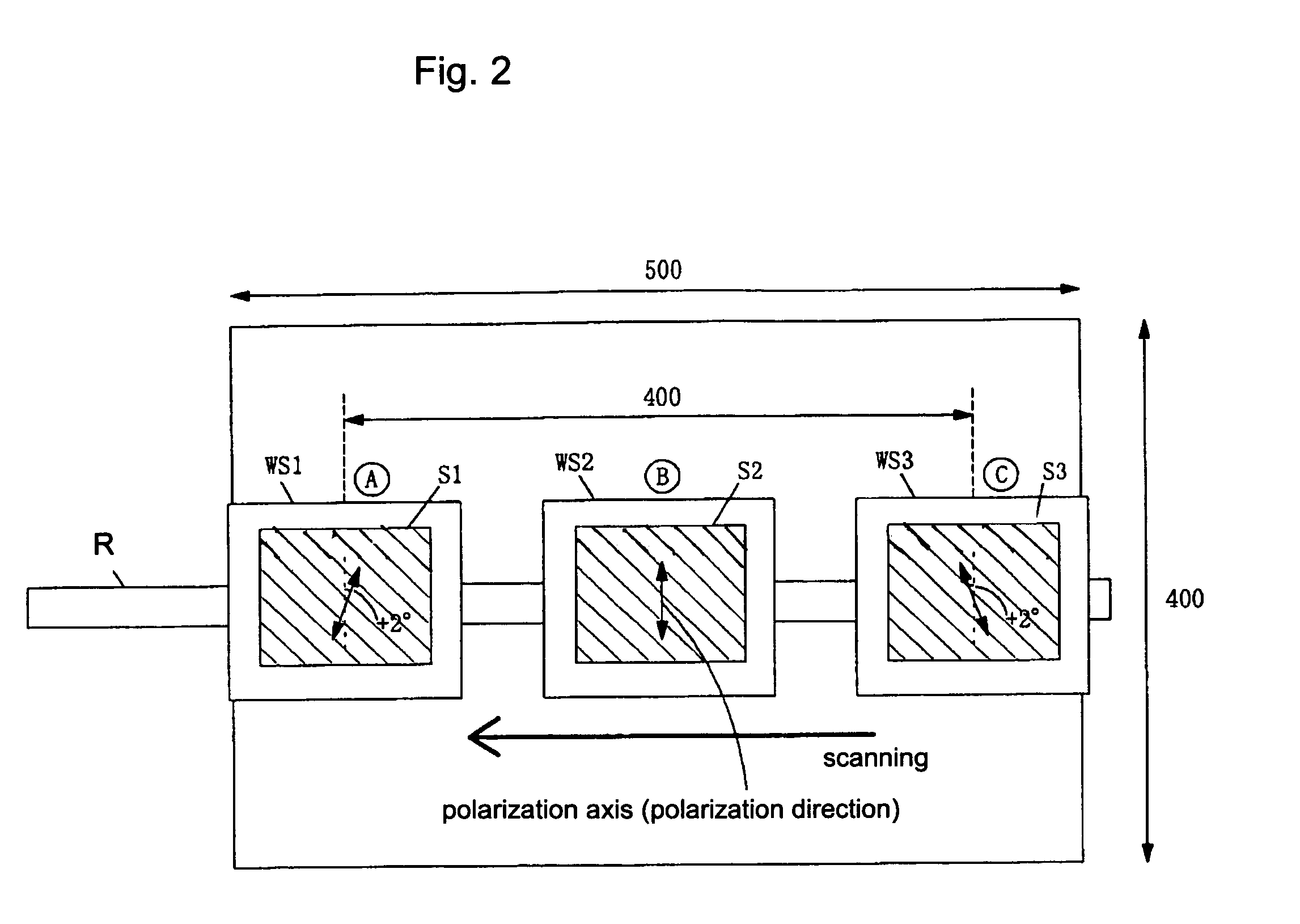
[0028]With the invention, it was confirmed using the test described below that, by moving the alignment layers in the direction in which the deviations of the polarization axis are cancelled, alignment of the alignment layers in the desired direction is enabled.

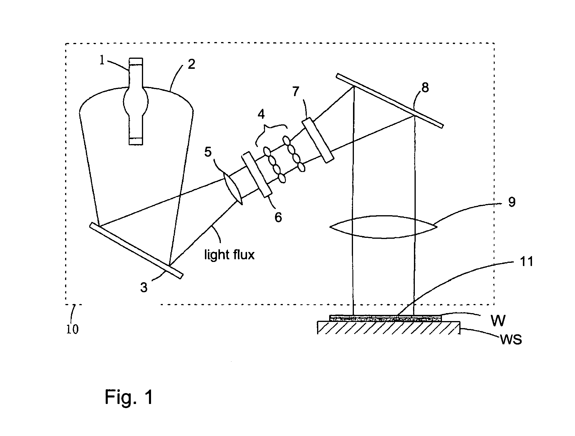
[0029]FIG. 1 shows the arrangement of a device for irradiation with polarized light for optical alignment in accordance with the invention that was used in the test. A lamp 1 emitting UV-containing light was focused by means of a focusing mirror 2. The light was then reflected by a first plane mirror 3, made into parallel light by an input lens 5 and was incident in a polarization element 6. The polarization element 6 comprised several glass plates inclined with respect to the optical axis by the Brewster angle.

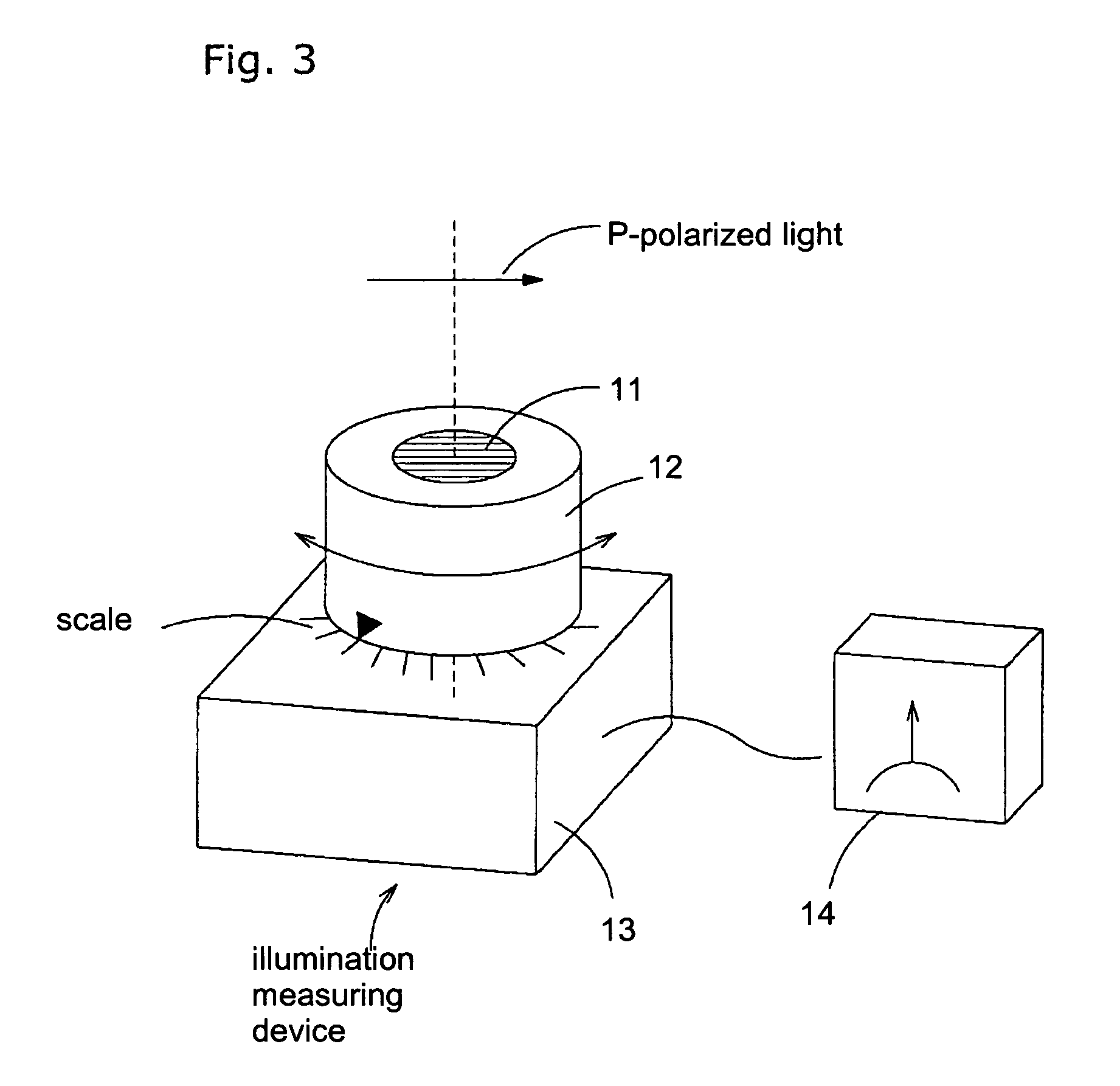
[0030]The light incident on the polarization element 6 was subjected to polarization separation. In the case of the above described polarization element 6, only P-polarized light emerged. The P-polarized light which em...


PUM

PropertyMeasurementUnit
speedaaaaaaaaaa
angleaaaaaaaaaa
transparentaaaaaaaaaa

Abstract

A process for optical alignment in which an alignment layer is irradiated with polarized light from a light source and optical alignment is carried out, and in which polarized light is emitted within the light irradiation area of the light source with differently aligned polarization axes. In doing so, the alignment layer and the light irradiation area are moved relative to one another so that the divergence of the polarization axes of the polarized light is essentially cancelled relative to one another and the direction of optical alignment in the alignment layer is made uniform.

Description

BACKGROUND OF THE INVENTION[0001]1. Field of Invention[0002]The invention relates to a process for optical alignment in which alignment layers of a liquid crystal display (LCD) element and an angle of view field compensation film which is installed in a liquid crystal cell are irradiated with polarized light, and in which optical alignment is performed. The invention relates especially to a process for optical alignment in which the alignment layers can be aligned in the desired direction even when optical alignment is being performed with deviations of the polarization axis for the polarized light which is radiated onto the alignment layers.[0003]2. Description of Related Art[0004]A liquid crystal display element is produced as follows:[0005]An alignment layer which is formed on the surface of a transparent substrate is subjected to treatment (alignment treatment) in which liquid crystals are aligned in the desired direction.[0006]Two transparent substrates are placed on top of one...

Claims


Application Information

Patent Timeline
Patent Type & Authority Patents(United States)
IPC IPC(8): C09K19/00C09K19/52
CPCG02F1/133788Y10T428/1005Y10T428/10C09K2323/00C09K2323/02G02F1/1337
Inventor SHIOTANI, SAYU
Owner USHIO DENKI KK
Learn More