Network with MAC table overflow protection

a network and table technology, applied in the field of computer networks, can solve problems such as inability to add different and unknown mac addresses, inability to protect network integrity, and inability to send thousands of different mac addresses to the same bridg

Active Publication Date: 2009-03-24
PROVEN NETWORKS LLC
View PDF10 Cites 106 Cited by
  • Summary
  • Abstract
  • Description
  • Claims
  • Application Information

AI Technical Summary

Problems solved by technology

An unfortunate development in the heavy use of networks in contemporary computing has been the many efforts of wrongdoers to either cause trouble to the operation of the network or to gain unauthorized access to network resources.
In the context of Ethernet networks, one malicious effort has been for a user to connect to the network and then flood a bridge with an unusually large number of frames, thereby adding different and unknown MAC addresses.
However, note that this approach has limitations, which are particularly victimized by the wrongdoer who floods the bridge per the prior art.
Given these limitations, a wrongdoer may send thousands of different MAC addresses to a same bridge in a relatively short time period.
Due to its size limitations, the MAC address forwarding table of the bridge will reach its address limits and if broadcasting will add a large amount of traffic to the network.
Moreover, once the MAC address forwarding table fills, the bridge having that table no longer accepts new MAC addresses, that is, it broadcasts all incoming traffic with unknown MAC addresses to the ports within the VLAN defined by the frame.
As a result, quickly the bridge is overwhelmed and it fails to perform its bridging functionality while also starting to drop frames from other sources.
The prior art approaches discussed above may reduce the chance for a bridge to be overburdened by flooding it with MAC frames, but there are also drawbacks to these approaches as may be ascertained by one skilled in the art.
As a drawback example of the first approach, legitimate frames may be received by the bridge, but if they include a destination MAC address that is not already in the bridge table, those frames will be dropped and therefore denied service by the network.
As a drawback example of the second approach, multiple instances of a registration are required in that a device may be periodically powered off and on, and it also permits a wrongdoer to flood the network and its bridges with numerous registration frames.

Method used


Image

  • Network with MAC table overflow protection
  • Network with MAC table overflow protection
  • Network with MAC table overflow protection

Examples


Embodiment Construction

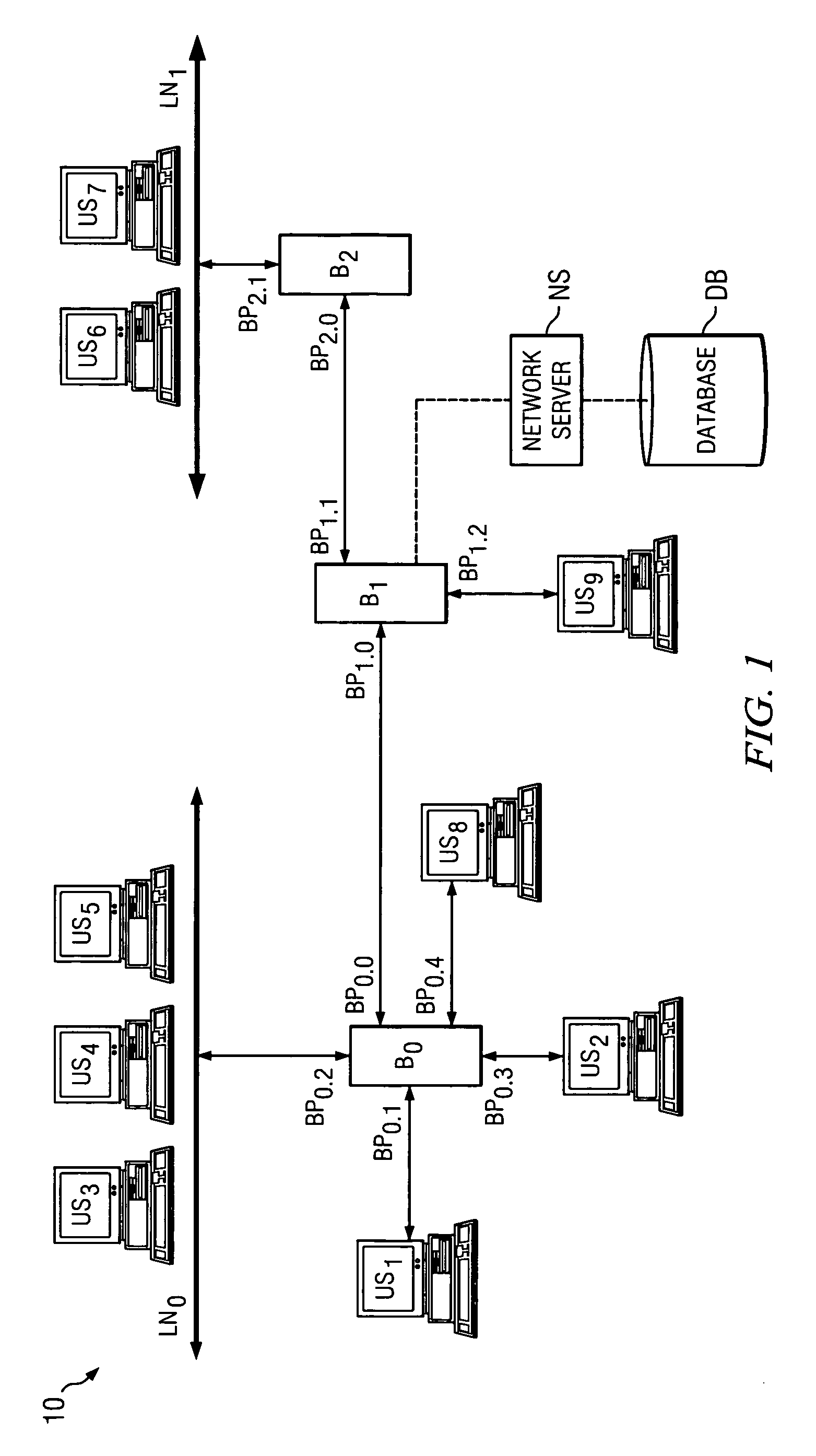
[0017]FIG. 1 illustrates a block diagram of a network system 10 into which the preferred embodiments may be implemented. In general at the level illustrated in FIG. 1, each item in system 10 is known in the art, where the nodes shown therein may be constructed using various forms of hardware and software programming to perform steps consistent with the discussions in this document. However, as detailed later, the methodology of operation as well as certain functions added to the bridge nodes provide for the preferred embodiments and improve system 10 as a whole, and such methodology and functionality may be readily added into the existing hardware and software programming of a system such as system 10. Indeed, as a result, the preferred embodiments are flexible and scalable to different sized networks.

[0018]System 10 generally represents a bridged network, such as an Ethernet network, that includes a number of nodes. In the context of Ethernet, some of the nodes may be referred to a...


PUM


Abstract

A method of operating a bridge node (B0) in a network system. The bridge node comprises a plurality of ports (BP0.x). The method comprises a step of receiving a frame (240), from a device in the network system and other than the bridge node, at a port in the plurality of ports. The frame comprises a source network address. The method is also responsive to at least one condition (250, 260) associated with the port in that the method stores the source address in a forwarding table associated with the bridge if the at least one condition is satisfied. The at least one condition comprises whether the frame was received within a time window Tw of when a threshold number of previous frames were received at the port and their respective source network addresses were stored in the table.

Description

CROSS-REFERENCES TO RELATED APPLICATIONS[0001]This application claims priority under 35 U.S.C. § 119 of U.S. Provisional Application No. 60 / 619,330, filed Oct. 15, 2004.STATEMENT REGARDING FEDERALLY SPONSORED RESEARCH OR DEVELOPMENT[0002]Not Applicable.BACKGROUND OF THE INVENTION[0003]The present embodiments relate to computer networks and are more particularly directed to a network with MAC table overflow protection.[0004]Ethernet networks have found favor in many applications in the networking industry and for various reasons. For example, Ethernet is a widely used and cost effective medium, with numerous interfaces and speed capability up to the 10+ Gbps range. Ethernet networks may be used in applications that are incorporated at a single location by a single entity such as a company or the like, or the entity as an alternative may couple various local area networks (“LANs”) together to form a larger network, sometimes referred to as a wide area network (“WAN”). Still further, E...

Claims


Application Information

Patent Timeline
Patent Type & Authority Patents(United States)
IPC IPC(8): H04L12/26H04L12/28
CPCH04L12/462H04L49/50H04L63/1466H04L63/1458H04L2463/145
Inventor GE, ANCHIRUVOLU, GIRISHALI, MAHER
Owner PROVEN NETWORKS LLC
Why Eureka
Try Eureka