Interface cable

a technology of interface cable and oximetry system, which is applied in the field of pulse oximetry system 100, can solve the problem that it is not possible to prevent the use of both a shared led pinout sensor and a separate id pinout sensor with the same host instrumen

Active Publication Date: 2009-03-24
JPMORGAN CHASE BANK NA
View PDF171 Cites 737 Cited by
  • Summary
  • Abstract
  • Description
  • Claims
  • Application Information

AI Technical Summary

Benefits of technology

[0008]A host instrument 510 that is configured to read an ID element 430 over ID lines 534 that are separate from the LED drive lines 532, as described with respect to FIGS. 4-5, is incompatible with a sensor 200 (FIG. 3) having an ID element 230 (FIG. 3) wired in parallel with the LEDs 210 (FIG. 3), i.e. a sensor 200 (FIG. 3) having shared LED pinouts 240 (FIG. 2), as described with respect to FIGS. 2-3. A conversion cable that provides a mechanism for connecting a shared LED pinout sensor to a host instrument configured for a separate ID element p...

Problems solved by technology

A conversion cable, however, does not prevent both a shared LED pinout sens...

Method used


Image

  • Interface cable
  • Interface cable
  • Interface cable

Examples


Embodiment Construction

System Overview

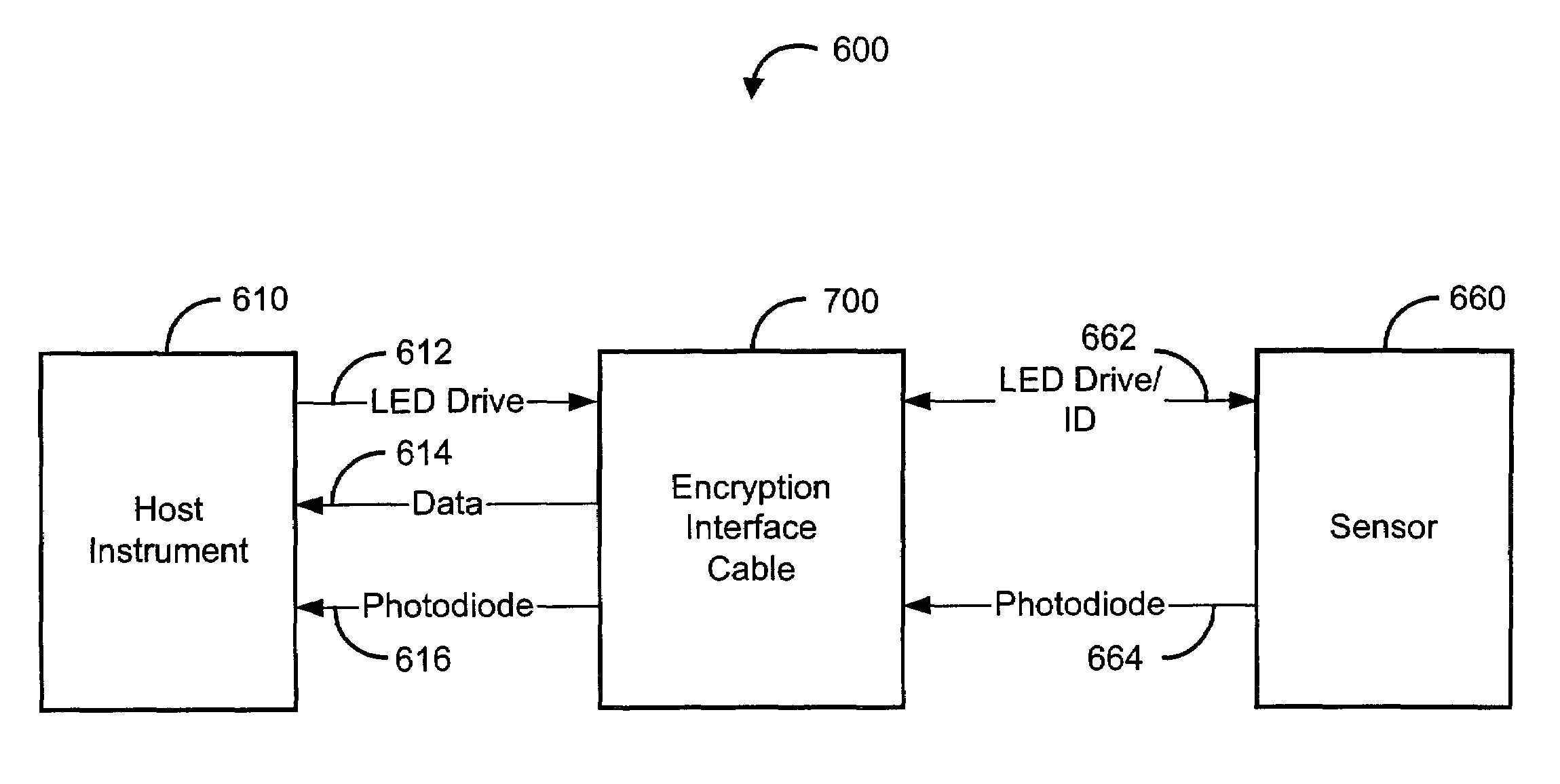
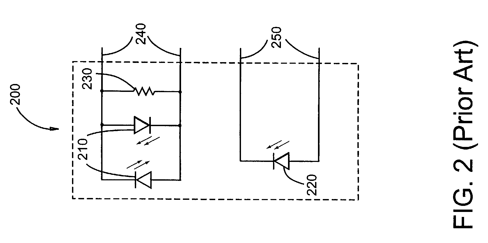
[0026]FIG. 6 illustrates a pulse oximetry system 600 having a host instrument 610, an encryption interface cable 700 and a sensor 660. The sensor 660 may be a shared LED pinout sensor, as described with respect to FIG. 2 above, and the host instrument 610 may be compatible with a separate ID pinout sensor as described with respect to FIG. 5, above. That is, in one embodiment, the host instrument 610 is configured for separate LED drive lines 612 and separate ID (“data”) lines 614, and the sensor is configured for shared LED drive / ID lines 662.

[0027]As shown in FIG. 6, an encryption interface cable 700, like a conversion cable, such as described in U.S. Pat. No. 6,349,228 referenced above, allows an otherwise incompatible shared LED pinout sensor 660 to be used with a host instrument 610 configured for a separate ID pinout sensor. However, unlike a conversion cable, one embodiment of an encryption interface cable 700 advantageously allows only authorized shared LED pin...


PUM


Abstract

An interface cable is configured to connect a host instrument to a physiological sensor. The interface cable has an ID signal input from the sensor and a LED drive signal input from the host instrument sensor port. The interface cable also has a data signal output to the host instrument sensor port. The LED drive signal and the data signal provide an encrypted handshake to and from the host instrument. The handshake is responsive to the ID signal so as to enable normal operation of the host instrument and the sensor.

Description

REFERENCE TO RELATED APPLICATION[0001]The present application claims priority benefit under 35 U.S.C. §119(e) from U.S. Provisional Application No. 60 / 381,393, filed May 16, 2002, entitled “Encryption Interface Cable,” and from U.S. Provisional Application No. 60 / 361,233 filed Mar. 1, 2002, entitled “Encryption Interface Cable,” which are incorporated herein by reference.BACKGROUND OF THE INVENTION[0002]Pulse oximetry is a widely accepted noninvasive procedure for measuring the oxygen saturation level of arterial blood. FIG. 1 illustrates a pulse oximetry system 100 having a sensor 200 attachable to a patient 10, a host instrument 310 for monitoring oxygen saturation and pulse rate, and a patient cable 350 that connects the sensor 200 and the host instrument 310. The sensor 200, can be attached to an adult patient's finger or an infant patient's foot, for example.[0003]FIG. 2 illustrates a sensor 200 having both red and infrared LEDs 210 and a photodiode detector 220. The sensor 200...

Claims


Application Information

Patent Timeline
IPC IPC(8): H04L9/00A61B5/00
CPCA61B5/14551A61B5/6826A61B5/6838A61B2560/045A61B2562/08A61B2562/222
Inventor AL-ALI, AMMAR
Owner JPMORGAN CHASE BANK NA
Why Eureka
Try Eureka