Non-return device

a non-return device and water trap technology, applied in mechanical equipment, functional valve types, transportation and packaging, etc., can solve the problems of difficult installation and maintenance, occupying a significant amount of space, and conventional water traps not having the ability to admit air into the waste drainage system

Inactive Publication Date: 2009-03-31
HEPWORTH BUILDING PROD
View PDF11 Cites 20 Cited by
  • Summary
  • Abstract
  • Description
  • Claims
  • Application Information

AI Technical Summary

Benefits of technology

[0015]means holding the said walls spaced from one another at an end of the device to define an inlet for ingress of fluid to the interface of said members, whereby in-flowing fluid will force the said members apart to permit flow between them from the inlet and the other end of the device, whereas fluid flow in the opposite direction is prevented by the close surface contact between the members;
[0017]In a preferred embodiment, the outlet portion has a smaller diameter than the body portion. The two may be joined by an intermediate portion which tapers from the body portion down to the outlet portion. By such an arrangement, the device can accommodate wall members having dimensions that provide a desired flow characteristic, whilst the outlet portion can be directly connected to a fitting having a smaller diameter than that of the body portion. This removes the need for an adapter between the device and the fitting, yet provides an uninterrupted surface for discharging fluid to flow over, thereby preserving the best possible flow characteristics and avoiding the collection of debris or stagnant water.
[0021]means holding said wall spaced apart from one another at an end of the device to define an inlet for ingress of fluid to the interface of said members, whereby in-flowing fluid will force said members apart to permit flow between them from the inlet and to the other end of the device, whereas fluid flow in the opposite direction is prevented by the close surface contact between the members;
[0024]Preferably, the means holding the walls spaced apart from one another is axially movable relative to the body portion, so as to enable the compression of the wall members therebetween. Preferably, the means holding the walls spaced apart is in the form of an annular sleeve which is located coaxially within the tubular body portion. Preferably, the annular sleeve has an end face which is adapted to abut the end of a component to which the device is to be attached, thereby experiencing an axial displacement relative to the body portion, as the body portion is axially drawn towards the component during attachment thereto. Preferably, the end face comprises a compression seal, so as to effect a seal between the component and the said inlet upon mounting. In one particularly preferred embodiment, the sleeve is provided at an axial inlet end of the body portion and surrounded by a nut, which can be screwed on to a component to which the device is to be fitted, thereby drawing the body portion axially towards the component in the desired manner. Such a preferred embodiment enables the device to be installed quickly and efficiently, using only one hand. Furthermore, the device can easily be demounted.

Problems solved by technology

Water traps, although simple and effective, have disadvantages; in particular, they occupy a significant amount of space and may be difficult to install and maintain where space is limited.
In addition to the foregoing disadvantages, conventional water traps do not have the ability to admit air into the waste drainage system.
Where such conventional waste traps are used, sinks and baths are known to gurgle.
This gurgling results from the waste drainage system struggling to equalize pressure differences within itself as “plugs” of water make their way through its pipework, creating positive pressure in front whilst leaving vacuums in their wakes.
A gurgling sink in its own right may be regarded as mildly irritating; however, once the water from the trap has been sucked out.
The bathroom or kitchen is then open to the drain and consequently very smelly, and even dangerous.
This is a particular problem with certain types of shared dwelling, where there are long falls of water from sinks, baths, and WCs on a higher floor, generating large pressure changes in the system on lower floors.

Method used


Image

  • Non-return device
  • Non-return device
  • Non-return device

Examples


Embodiment Construction

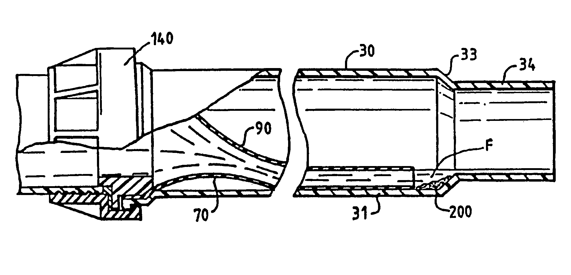
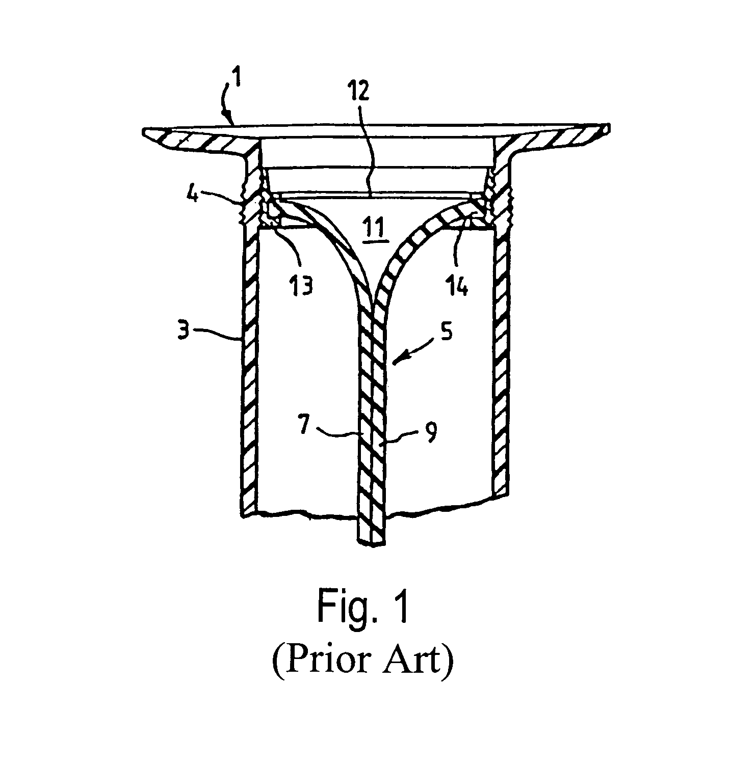
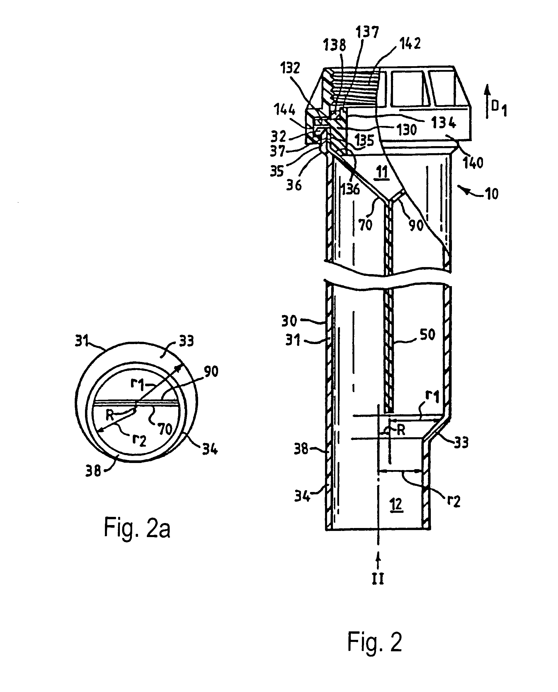
[0037]FIGS. 2 and 3 show in vertical cross-section a first non-return device embodying the invention. From these figures, it will be seen that the device has general similarity with the prior art device of FIG. 1. A thin-walled lie-flat elastomeric tube 50 is located inside a pipe 30. The tube 50 comprises two opposite flat walls 70, 90 which are connected to each other, with sharp creases where the flat walls meet, extending along the length of the tube. The tube is manufactured in such a way that, in its normal relaxed state, the opposite flat walls 70, 90 lie in face-to-face contact with one another at a light pressure, due to the resilience of the material of the tube 50.

[0038]The lie-flat tubing 50 is made from silicone rubber and has a wall thickness of 0.28 mm. The walls have a width (measured in a direction perpendicular to the page in FIG. 2) of 44 mm. The tubing should be resistant to temperatures of less than 0° C. and up to 100° C. It should also be chemically resistance...


PUM


Abstract

A non-return device (10) comprises a flat silicone rubber tubing (50) defining a pair of walls (70, 90) which separate to admit fluid in a forward direction but remain together to block fluid flow in a reverse direction. A tubular body (30) surrounds the tubing (50) and comprises an off-set outlet (34) to provide an uninterrupted fluid flow surface for use in a non-vertical orientation. The tubing (50) is mounted on a cartridge (130) which moves axially within the tubular body and compresses the tubing against the tubular body to effect a seal when the device is mounted on an outlet. The tubing (50) provides good operational characteristics and sensitivity as a consequence of having a wall thickness which is 0.3% to 3% of its width.

Description

SUMMARY OF THE INVENTION[0001]1. Field of the Invention[0002]This invention relates to a non-return device, with particular but not exclusive reference to waste and / or odour traps for domestic and other plumbing.[0003]2. Description of the Related Art[0004]Conventionally, sinks, baths, shower cubicles and the like are provided with waste traps to provide a barrier between the appliance and the waste pipe. These are intended to prevent the escape of unhealthy emissions and unpleasant odours.[0005]The most usual form of waste trap is a bend containing water. Water held in the bend prevents the release of gases and vapours from the waste pipe, whilst permitting passage of water and solids.[0006]Water traps, although simple and effective, have disadvantages; in particular, they occupy a significant amount of space and may be difficult to install and maintain where space is limited. They not infrequently become blocked or dry out and can back-siphon. Moreover, they act as collecting poin...

Claims


Application Information

Patent Timeline
Patent Type & Authority Patents(United States)
IPC IPC(8): F16K15/14E03C1/122E03C1/288E03C1/298
CPCE03C1/122E03C1/288E03C1/298F16K15/147Y10T137/7886Y10T137/7882F16K15/1472
Inventor CURRID, STEPHEN
Owner HEPWORTH BUILDING PROD
Why Eureka
Try Eureka