Tire with turned down ply construction

a technology of ply construction and tires, which is applied in the field of pneumatic tires, can solve the problems of significant reduction of material expenses of a manufacturer engaged in high-volume tire production, and achieve the effects of reducing rim indentation, reducing material expenses, and increasing the support of tires

Inactive Publication Date: 2009-03-31
THE GOODYEAR TIRE & RUBBER CO
View PDF28 Cites 8 Cited by
  • Summary
  • Abstract
  • Description
  • Claims
  • Application Information

AI Technical Summary

Benefits of technology

[0004]The present invention provides a tire utilizing an outside-in ply construction which torques the tire bead into the rim of the wheel to which it is mounted. The tire's outside-in ply construction also serves to pull down the toe of the tire, improving contact between the tire and the rim and to reduce rim indentation. The outside-in ply construction allows the rim to provide greater support for the tire. The reverse pulling direction of the ply reduces toe lifting and facilitates the use of a smaller bead and reduces the tire's weight and material usage.

Problems solved by technology

Even a small decrease in the amount of materials needed to produce a tire can result in significantly decreased material expenses for a manufacturer engaged in high-volume tire production.

Method used


Image

  • Tire with turned down ply construction
  • Tire with turned down ply construction
  • Tire with turned down ply construction

Examples


first embodiment

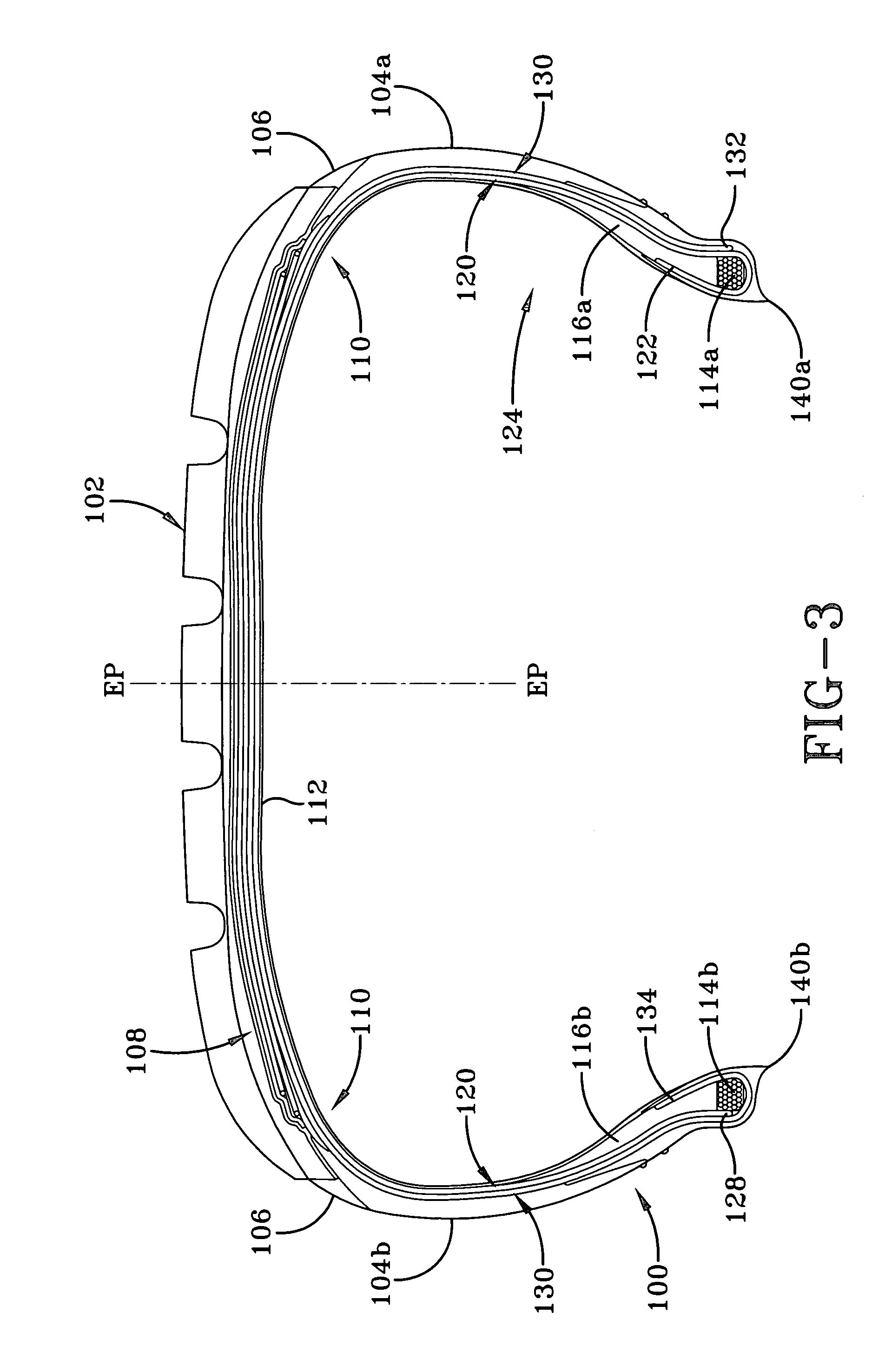
[0039]With particular reference to FIG. 3, there is illustrated a cross-sectional view of a tire 100 of the present invention. The tire 100 has a tread portion 102 and a pair of sidewalls 104a,b wherein the sidewalls are connected to the tread portion by shoulder regions 106. The tire may have one or more reinforcing belts 108 which laterally extend under the tread 102. A carcass 110 of the tire includes an innerliner 112 which extends from bead 114a to bead 114b. The carcass further comprises a first ply layer 120 and a second ply layer 130. The carcass may comprise additional ply layers if needed. The first ply 120 has a reverse turned up end with the end 122 of the ply located on the interior portion 124 of the tire. The first ply 120 extends down from the turned up end 122, wraps along the outer portion of bead 114a, up the sidewall 104a, under the tread 102, down the sidewall 104b with a second end 128 extending down to bead 114b. The second end 128 does not wrap around bead 11...

second embodiment

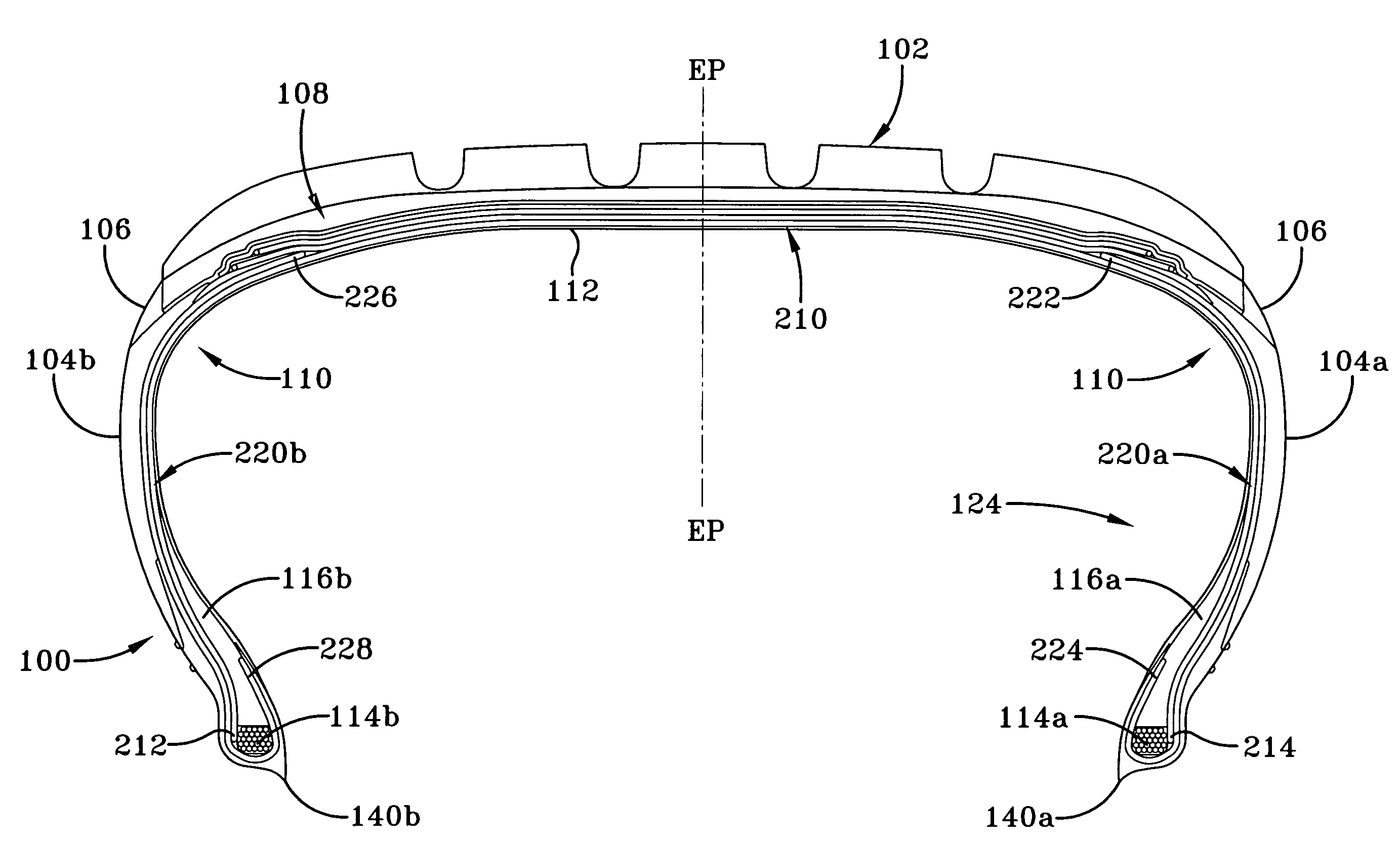
[0045]A cross-sectional view of a tire assembly 200 is shown in FIG. 5. The tire assembly 200 includes all of the tire components as shown in FIG. 3 and described above, except that a different ply construction is utilized. Instead of ply layers 120,130 as described above, ply layers 210,220 are utilized. Ply layer 210 is located radially outward of the inner liner 112, and has a first end 212 located adjacent bead 114b. The ply layer 210 extends up from the first end 212, up the sidewall 104b, under the tread 102, down the other sidewall 104a and extends down to the other bead 114a. The ends 212,214 of ply layer 210 do not wrap around either bead.

[0046]A second layer of sidewall ply 220a,b is located radially outward of the first layer of ply 210 in the sidewall and shoulder area. A first sidewall ply 220a has a first end 222 located under the inner tread belt 108 and extends down the sidewall 104a, wraps around the bead 114a and optional apex 116a, and has a turned up end 224 loca...

third embodiment

[0050]A cross-sectional view of a tire assembly 300 is shown in FIG. 7. The tire assembly 300 includes all of the tire components as shown in FIG. 5 and described for tire assembly 200 above, except that shoulder inserts are additionally utilized for a run flat or extended mobility tire construction. A first shoulder insert 310a,b is located between the liner 112 and the bead to bead ply 210 in the shoulder of the tire assembly 300. The shoulder insert extends from near the top of apex 116 to near the edge of the belts 108 in the shoulder area. An optional second set of shoulder inserts 320a,b are located between the bead to bead ply 210 and the shoulder plies 220a,b. The second set of shoulder inserts 320a,b extend from near the edge of belts 108 to near the apex 116a,b.

[0051]The layout of the tire components is shown in FIGS. 8A and 8B. As shown in FIG. 8A, first an inner liner 112 is laid up on the midsection of a tire building drum 200. Next, a first and second toeguard 140a, 1...


PUM


Abstract

A tire having an outside-in ply construction is provided which torques the tire bead into the rim of the wheel to which it is mounted. The tire has first and second axially-spaced bead cores, a carcass having at least one belt extending under a tread, and a first ply layer having first and second ends. A first end is located axially outside and adjacent a first bead core, and a second end folds from a position axially outside a second bead core to a position axially inside and around the second bead core. The carcass further comprises a second ply layer having first and second ends, a first end is located axially outside and adjacent the second bead core, and a second end that folds from a position axially outside a first bead core to a position axially inside and around the first bead core. The tire may also comprise a first and second axially-spaced bead core, a carcass having at least one belt extending under a tread, and a first ply layer having first and second ends, a first end is located axially outside and adjacent a first bead core, and a second end that is located axially outside and adjacent a second bead core. The carcass further comprises first and second shoulder ply layers each shoulder ply layer having first and second ends, a first end is located under the tread belt, the shoulder ply extending down the side wall region with the second end folding from a position axially outside a respective bead core to a position axially inside and around the bead core.

Description

FIELD[0001]This invention relates to pneumatic tires, and more particularly, the invention relates to ply constructions for tires.BACKGROUND OF THE INVENTION[0002]Modern passenger tires are typically constructed as shown in FIGS. 1 and 2, wherein the turn-up ends 20 of the ply wrap around the bead cores 26 in an inside-out fashion with reference to the interior 30 and exterior 32 of the tire. When the tire is inflated, the radial ply 15 exerts an inherent upward force F1 as shown in FIG. 1. The force F1 exerted by the radial ply 15 causes the bead cores 26 to rotate in a direction R1, causing the toe 36 to lift away from the rim (not shown). This configuration is standard on the vast majority of tire constructions.[0003]It is known in the prior art to utilize an “outside-in” configuration wherein the ply is wrapped around the bead so that the turn up end is located on the inside of the tire or inside the apex. The reversing of the location of the ply turnup results in the reversing ...

Claims


Application Information

Patent Timeline
Patent Type & Authority Patents(United States)
IPC IPC(8): B60C15/00B60C9/00
CPCB29D30/32B60C15/0018B60C15/0072Y10T152/10855Y10T152/10864Y10T152/10819
Inventor DOWNING, DANIEL RAYBENZING, II, JAMES ALFREDLOSEY, ROBERT ALLEN
Owner THE GOODYEAR TIRE & RUBBER CO
Why Eureka
Try Eureka