Rotor aircraft tilting hub with reduced drag rotor head and mast

a technology of rotor head and mast, which is applied in the direction of machines/engines, marine propulsion, vessel construction, etc., can solve the problems of mast and masthead assembly, drag during high-speed flight, etc., and achieve the effect of reducing oscillatory feathering

Active Publication Date: 2009-03-31
JAUNT AIR MOBILITY LLC
View PDF10 Cites 23 Cited by
  • Summary
  • Abstract
  • Description
  • Claims
  • Application Information

AI Technical Summary

Benefits of technology

[0006]In this invention, the rotary aircraft has a spinner housing that encloses the masthead. The spinner housing has two half portions that are movable relative to each other about the feathering axis of each of the blades during collective pitch change. The root of each blade terminates and is rigidly attached to at one of the half portions. A collective pitch mechanism causes each half portion of the spinner hou

Problems solved by technology

The control mechanisms extend alongside the mast, creating a fairly larg

Method used


Image

  • Rotor aircraft tilting hub with reduced drag rotor head and mast
  • Rotor aircraft tilting hub with reduced drag rotor head and mast
  • Rotor aircraft tilting hub with reduced drag rotor head and mast

Examples


Embodiment Construction

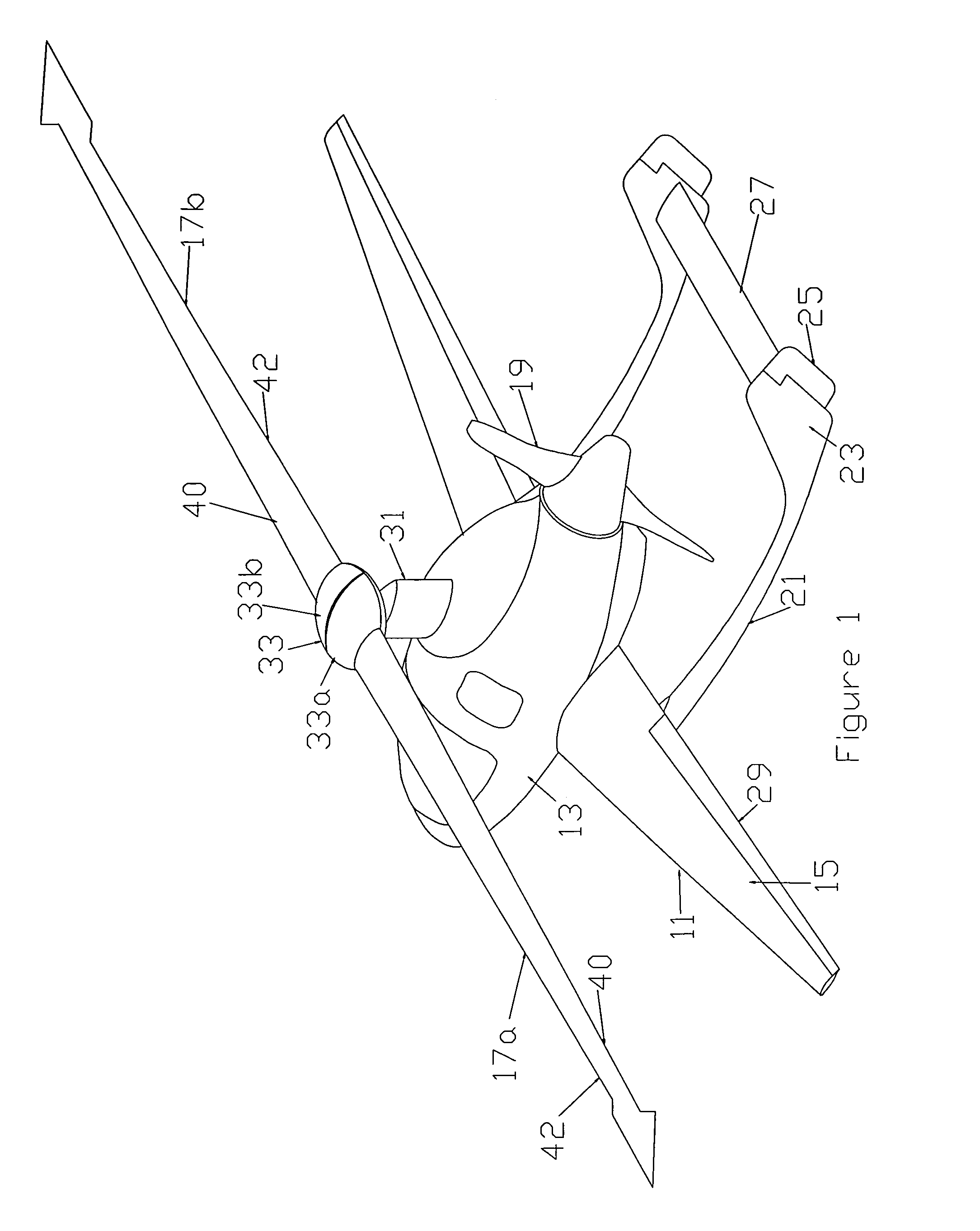
[0019]Referring to FIG. 1, gyroplane 11 has a fuselage 13 and a pair of wings 15. A rotor having blades 17a, 17b is located above fuselage 13 for providing lift during takeoff, slow speed flight and landing. A propeller 19, which is shown as a pusher type but could be reversed, provides propulsion for horizontal flight. Propeller 19 is driven by the same engine that drives the rotor, and could be eliminated if the engine is a jet engine.

[0020]Gyroplane 11 has a pair of tail booms 21 with a vertical stabilizer 23 at the ends. A rudder 25 is located on the aft end of each vertical stabilizer 23. A movable elevator 27 may be mounted between stabilizers 23. Also, ailerons 29 may be located at the trailing edge of each wing 15.

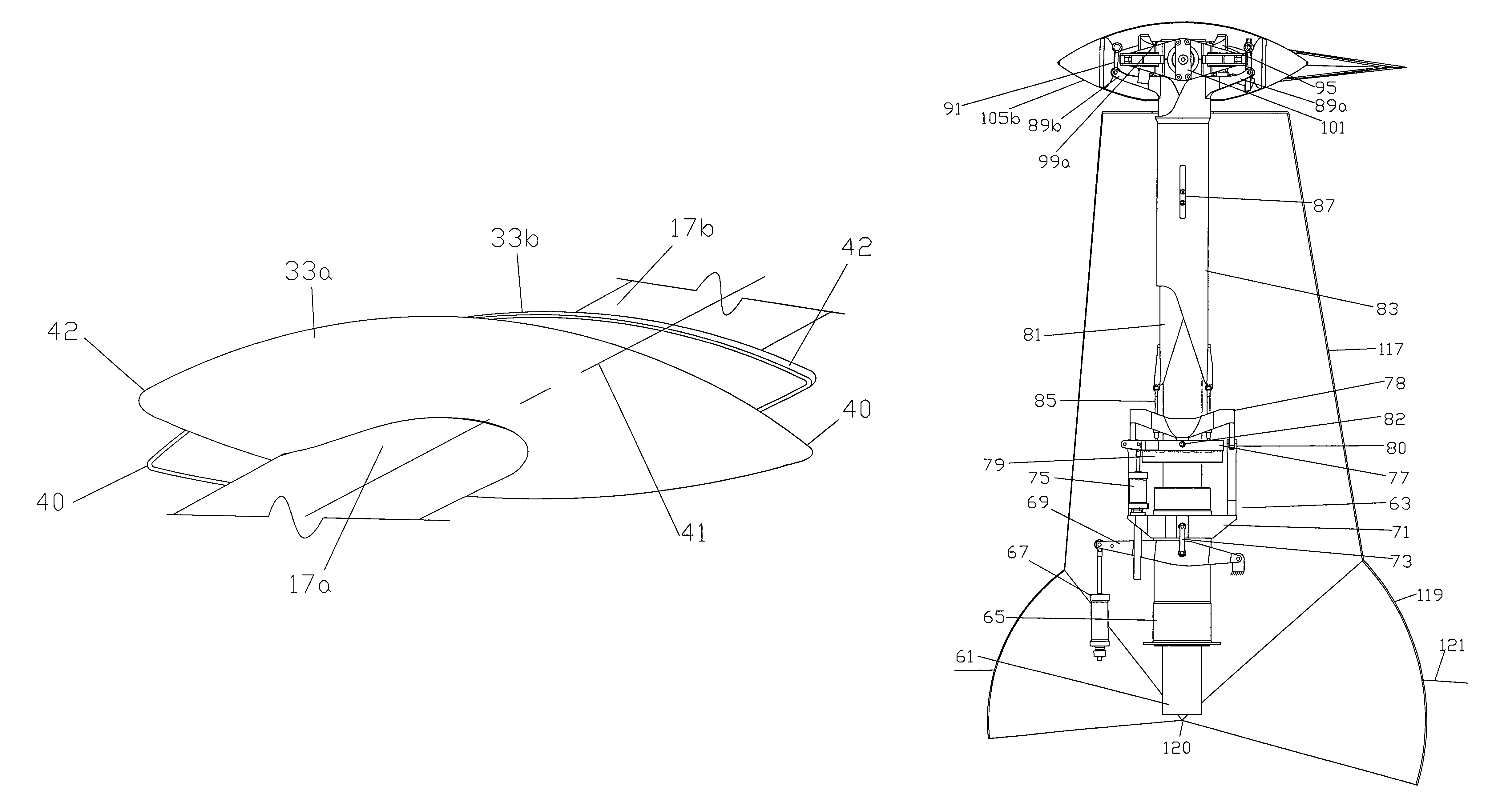
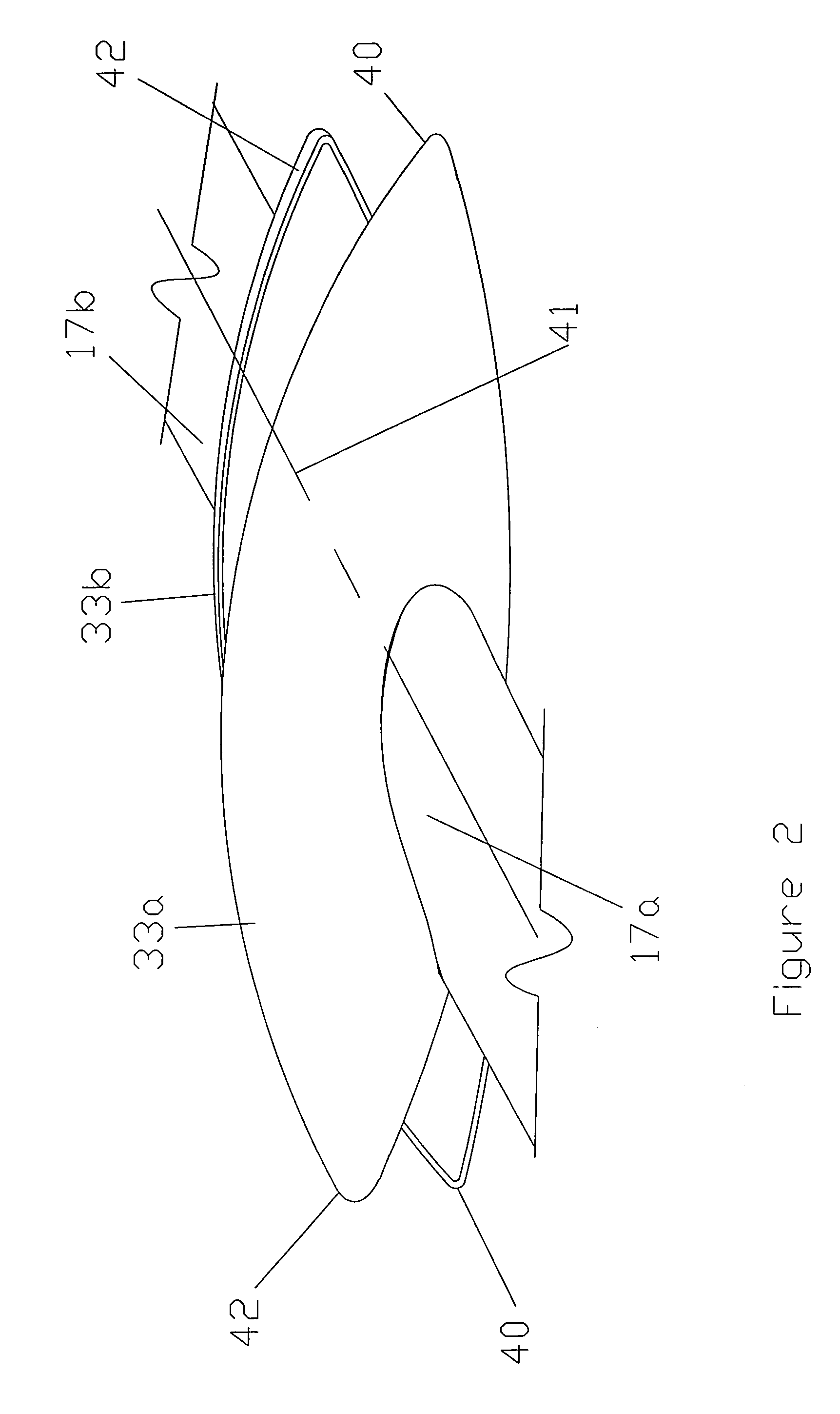
[0021]A mast fairing 31 encloses the mast assembly between fuselage 13 and rotor blades 17a, 17b. Also, in the preferred embodiment, a spinner housing 33 encloses the masthead. Spinner housing 33 has two half portions 33a and 33b. In the preferred embodiment, blade...


PUM


Abstract

A rotor aircraft has a tilting hub for cyclic control operated by either a tilting spindle or swash plate mounted to the upper end of the drive shaft. A spinner housing with two separate half portions encloses the hub. The blades of the rotor have root portions that are integrally joined to the separate half portions. During a collective pitch change, the half portions rotate relative to each other, but at advance ratios greater than about 0.7, when the collective can be held constant, the spinner half portions can be in perfect alignment. Concentric control sleeves surround the drive shaft for changing collective pitch as well as cyclic pitch.

Description

CROSS REFERENCE TO RELATED APPLICATION[0001]This application claims the benefit of provisional application Ser. No. 60 / 628,395 filed Nov. 16, 2004.FIELD OF THE INVENTION[0002]This invention relates in general to rotor aircraft, and in particular to fairings and control devices for the rotor that are streamlined to reduce drag.BACKGROUND OF THE INVENTION[0003]One type of rotor aircraft has a rotor, at least one propeller, and wings. The rotor provides most of the lift during short or vertical takeoffs, slow speed flight, and landings, the wings provide most of the lift during cruise conditions. During cruise conditions, the rotor preferably free-wheels at a relatively slow speed. The rotor may be completely undriven in flight, or it may be driven for hovering. For take-offs with the undriven type, the pilot spins the rotor to a high speed while still on the ground. At liftoff, the rotor disengages from the engine, and the inertia of the rotor provides lift for a take-off. The propell...

Claims


Application Information

Patent Timeline
IPC IPC(8): B63H3/02
CPCB64C27/024B64C39/04
Inventor CARTER, JR., JAY W.ROBINSON, M. KEITHMITCHELL, GEORGE D.
Owner JAUNT AIR MOBILITY LLC
Why Eureka
Try Eureka