Clamping connection, connecting terminal arrangement and installation switching device

a technology of installation switching device and terminal arrangement, which is applied in the direction of clamped/spring connection, electrical equipment, connections, etc., can solve the problems of disadvantageous operator lever ratio, and achieve the effect of increasing the mechanical stability of the terminal connection

Inactive Publication Date: 2009-03-31
ABB PATENT GMBH
View PDF4 Cites 31 Cited by
  • Summary
  • Abstract
  • Description
  • Claims
  • Application Information

AI Technical Summary

Benefits of technology

[0008]Due to the fact that the clamping edge is located at the transition of the connecting end into the discharge area, the entire width of the conductor bar is available for the current flow from the connecting conductor, clamped to the clamping edge, to the discharge area so that a low contact resistance can be achieved.
[0010]In an exemplary embodiment of the disclosure, the clamping leg of the clamping spring can be longitudinally slotted for facilitating the clamping-on of two connecting conductors, so that two closely adjacent part-springs, which can be clamped independently of one another, are produced. Due to the fact that the two part-springs are close together, that is to say without having a separating, relatively large intermediate space or an intermediate web between them which is approximately in the centre, a further contribution is made towards a narrow construction of the terminal connection so that the terminal connection according to the disclosure can be installed in an installation switching device having only half a standard module width.
[0012]The obtuse angle between the first and the second part-clamping leg provides the advantage that an advantageous point of application for a spring actuating means is located in the vicinity of the bending edge. If it is placed into the vicinity of the bending edge between the first and the second part-clamping leg, the point of placement of the spring actuating means can have a greater distance from the point of rotation of the clamping leg at the arc piece without the maximum terminal opening which can be achieved as a result becoming smaller and without the spring actuating means being in the way of a connecting conductor having a large cross section. However, a greater distance between the point of placement and the point of rotation means a more advantageous lever ratio and thus a lower actuating force for the user. Thus, a further problem in previously known screwless connecting terminals in installation switching devices can be advantageously solved. This is because, for introducing a connecting conductor, the clamping leg is usually bent by means of an actuating means in such a manner that a window for introducing connecting conductors is produced between the clamping edge of the clamping leg and the clamping edge of the conductor bars. If connecting conductors having a large conductor cross section are to be inserted, it is necessary that the window becomes large enough. In the terminal connection according to EP 1 575 130, the point of application of the spring actuating means must come to lie relatively close to the bent piece of the clamping spring. Otherwise, the spring actuating means would be in the way of the connecting conductor. The consequence is, however, that a lever ratio is produced which is disadvantageous for the operator. The actuating force which has to be exerted by the user when pressing on the pressure area of the terminal cover part to open the terminal is correspondingly relatively large in clamping connections according to the prior art. A clamping connection according to the disclosure can reduce the actuating force.
[0016]According to a further embodiment, a discharge bar can also be moulded on at the free end of the other U-leg. The discharge bar can extend approximately perpendicularly to the other U-leg and the side of the connecting end opposite to the clamping edge can be supported on the discharge bar. From the conductor bar and the discharge bar, a closed terminal frame is thus produced which is stable in itself. This increases the mechanical stability of the terminal connection.
[0017]This is because it produces the advantage that the forces acting on the terminal connection during the insertion and detachment of the connection conductor are absorbed by it as a closed system. When the terminal connection according to the disclosure is installed in an installation switching device, connecting forces which are produced, for example, during the opening of the clamping contact by an actuating tool, are thus internally absorbed in the terminal frame and now only act on the support points of the terminal frame in the housing but not on other elements of the installation switching device.
[0020]This is not necessary when connecting terminal arrangements according to the disclosure are used in an installation switching device. In this case, the discharge area of the conductor bar of the terminal connection according to the disclosure in the connecting terminal arrangement according to the disclosure is used as calibration contact. Compared with the prior art, this saves both assembly parts—namely the additional covering parts—and production steps in the assembly so that a further advantage is obtained from the resultant simplification of assembly.

Problems solved by technology

The consequence is, however, that a lever ratio is produced which is disadvantageous for the operator.

Method used


Image

  • Clamping connection, connecting terminal arrangement and installation switching device
  • Clamping connection, connecting terminal arrangement and installation switching device
  • Clamping connection, connecting terminal arrangement and installation switching device

Examples


Embodiment Construction

[0034]In the figures, identical or identically acting components or elements are in each case provided with identical reference numbers even if they are configured in slightly modified form in different variants of the embodiment.

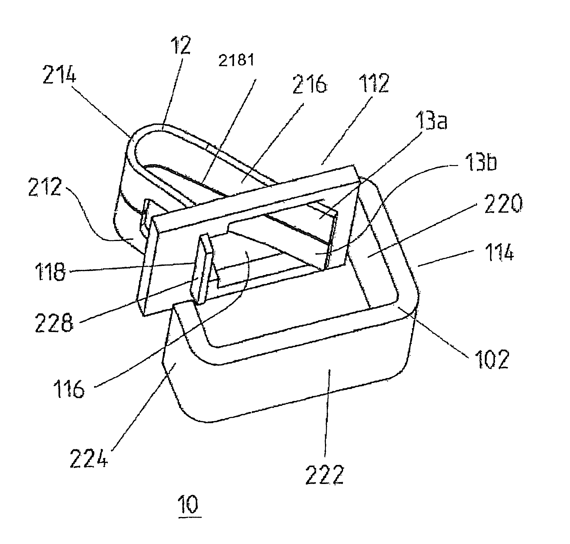
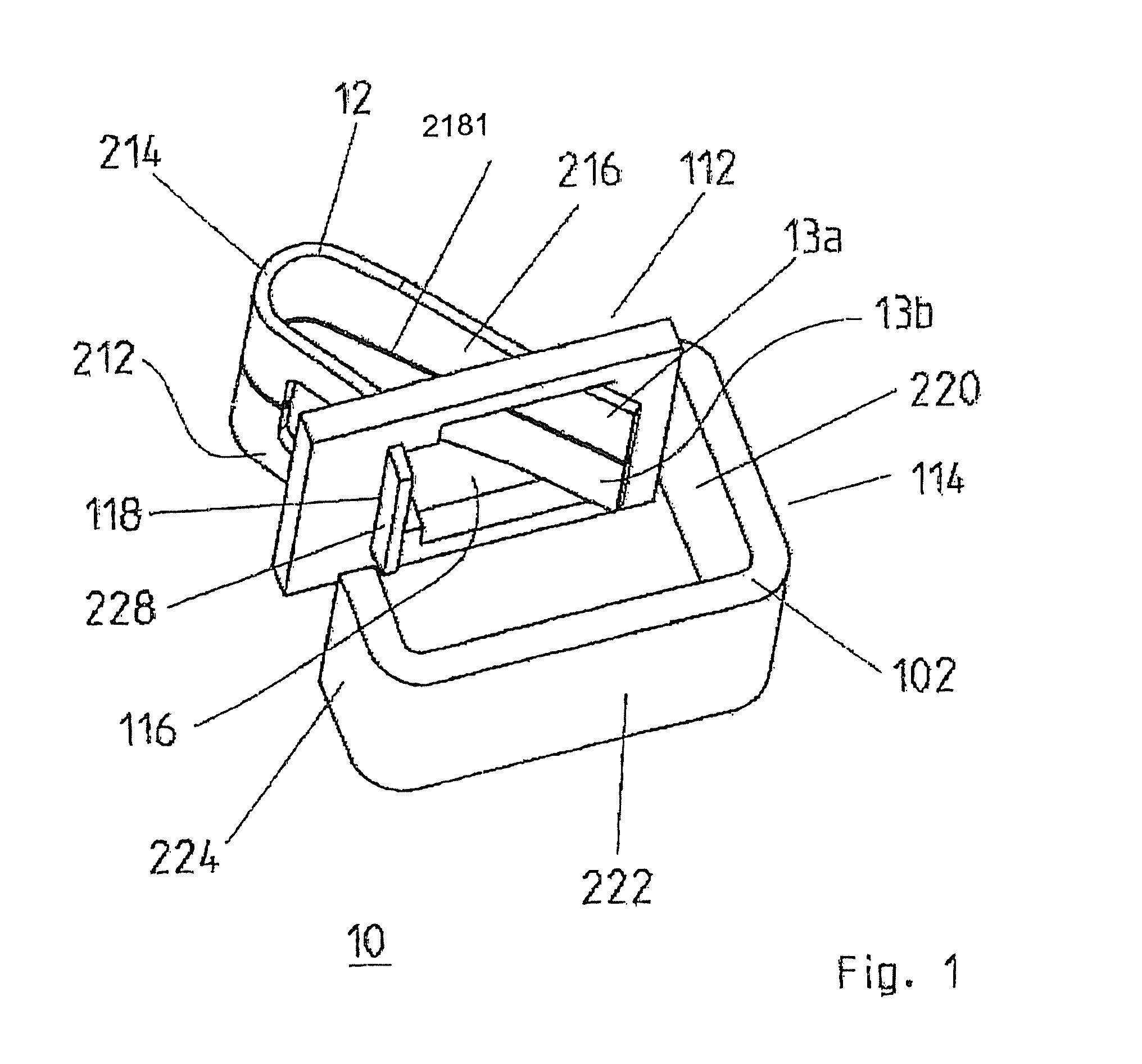
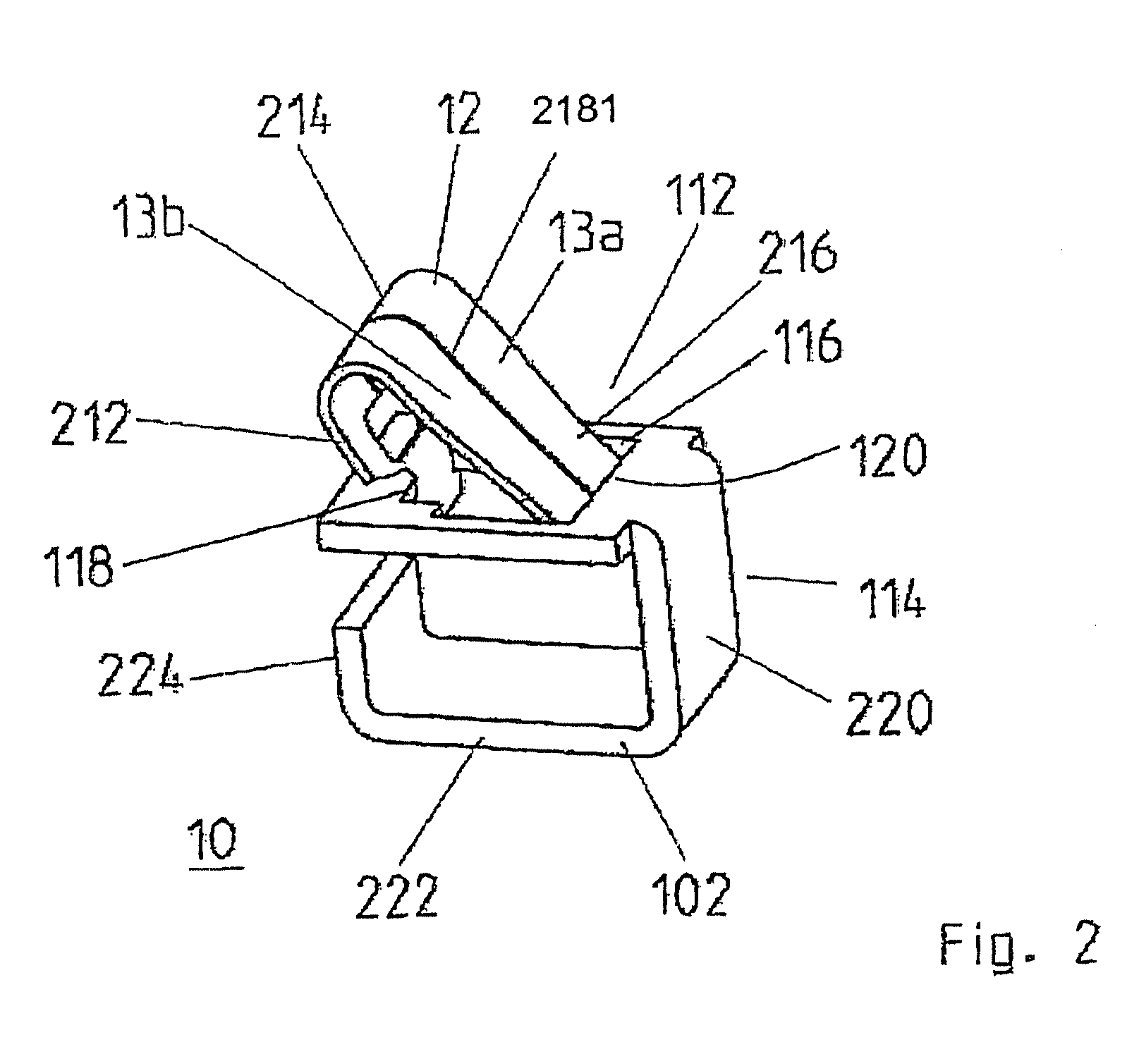
[0035]Initially, FIG. 1 will be considered. The terminal connection 10 comprises a conductor bar 102 and a clamping spring 12. The conductor bar 102 comprises a connecting end 112 and an adjoining discharge area 114. At the connecting end 112, it has a window-like opening 116 with a support edge 118 and a clamping edge 120 opposite the support edge 118. The clamping edge 120 is located at the transition of the connecting end 112 into the discharge area 114.

[0036]The clamping spring 12 has a support leg 212 with which it is supported on the support edge 118 of the conductor bar 102. The support can be effected in such a manner that the supporting leg 212 has at its free end an upward bend 228 with which it partially encloses the support edge 118 for the purp...


PUM


Abstract

Clamping connection for connecting a conductor to an installation switching device, comprising a clamping spring, acting on the conductor end as compression spring, for clamping tight the conductor end at an abutment, whereinthe clamping connection comprises a conductor bar with a connecting end and an adjoining discharge area,the conductor bar has at the connecting end a window-like opening with a support edge and a clamping edge, opposite the support edge, at the transition of the connecting end into the discharge area,the clamping spring has a support leg by means of which it is supported on the support edge of the conductor bar, andthe support leg is adjoined by an arc piece which is adjoined by a clamping leg, so that the conductor end can be clamped tight between the clamping leg and the clamping edge as abutment.

Description

RELATED APPLICATIONS[0001]This application claims priority under 35 U.S.C. §119 to German Application 10 2006 047 255.1 filed in Germany on Oct. 6, 2006, and to German Application 10 2007 044 262.0 filed in Germany on Sep. 17, 2007, the entire contents of which are hereby incorporated by reference in their entireties.TECHNICAL FIELD[0002]A clamping connection for connecting a conductor to an installation switching device, for example a circuit breaker, an earth-leakage circuit breaker or a motor protection switch, with a clamping spring, acting as compression spring on the conductor end, for clamping the conductor end to an abutment, and a connecting terminal arrangement and an installation switching device with a generic terminal connection.BACKGROUND INFORMATION[0003]From EP 1 575 130, a generic terminal connection is known in which a number of plug-in openings and a holding opening are present in a contact frame. The clamping spring is held at a first free end in the holding open...

Claims


Application Information

Patent Timeline
Patent Type & Authority Patents(United States)
IPC IPC(8): H01R4/48
CPCH01R4/4836H01R4/48365
Inventor EPPE, KLAUS-PETERTHIELEN, CAROLASTIEGER, ALBERTHACK, RICHARD
Owner ABB PATENT GMBH
Why Eureka
Try Eureka