Plug flow reactor and polymers prepared therewith

a technology of plug-flow reactor and polymer, which is applied in the direction of moving conduit heat exchanger, solid heating fuel, chemical/physical/physicochemical stationary reactor, etc., can solve the problems of affecting the operation of the reactor, and affecting the efficiency of the reactor

a technology of plug-flow reactor and polymer, which is applied in the direction of moving conduit heat exchanger, solid heating fuel, chemical/physical/physicochemical stationary reactor, etc., can solve the problems of affecting the operation of the reactor, and affecting the efficiency of the reactor

US7511101B2Inactive Publication Date: 2009-03-31FINA TECH

Image

  • Plug flow reactor and polymers prepared therewith
  • Plug flow reactor and polymers prepared therewith
  • Plug flow reactor and polymers prepared therewith

Examples


Embodiment Construction

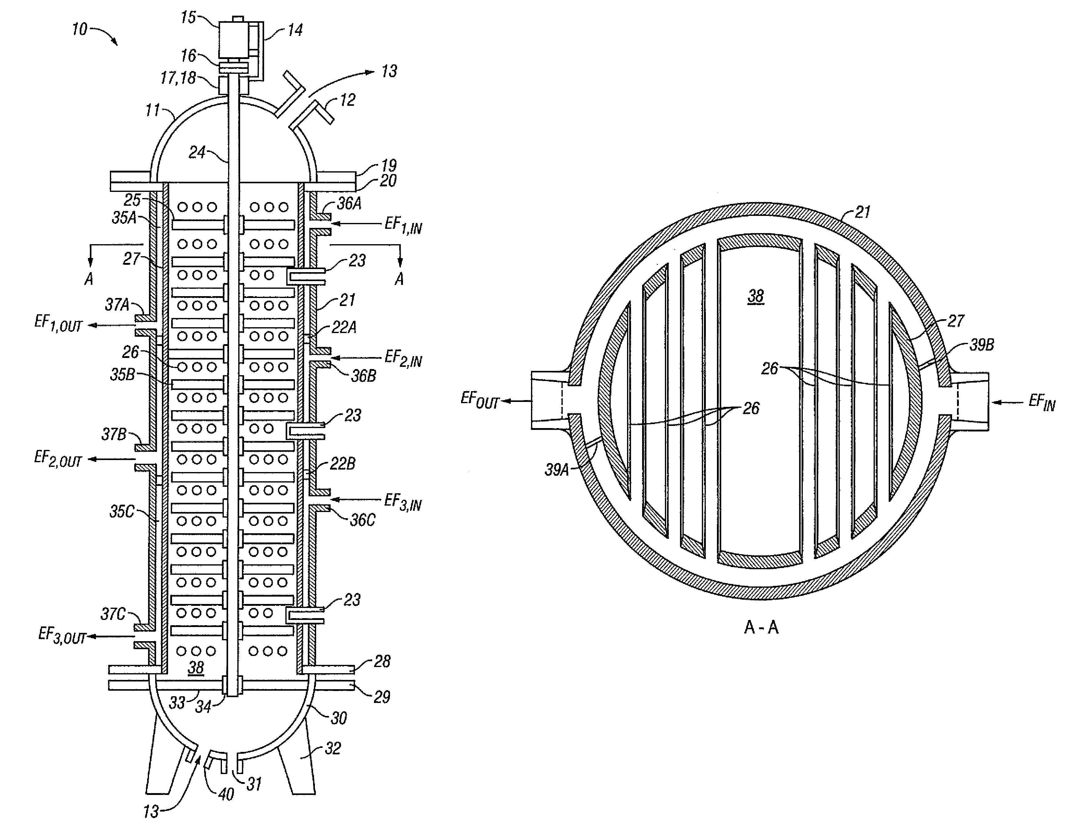
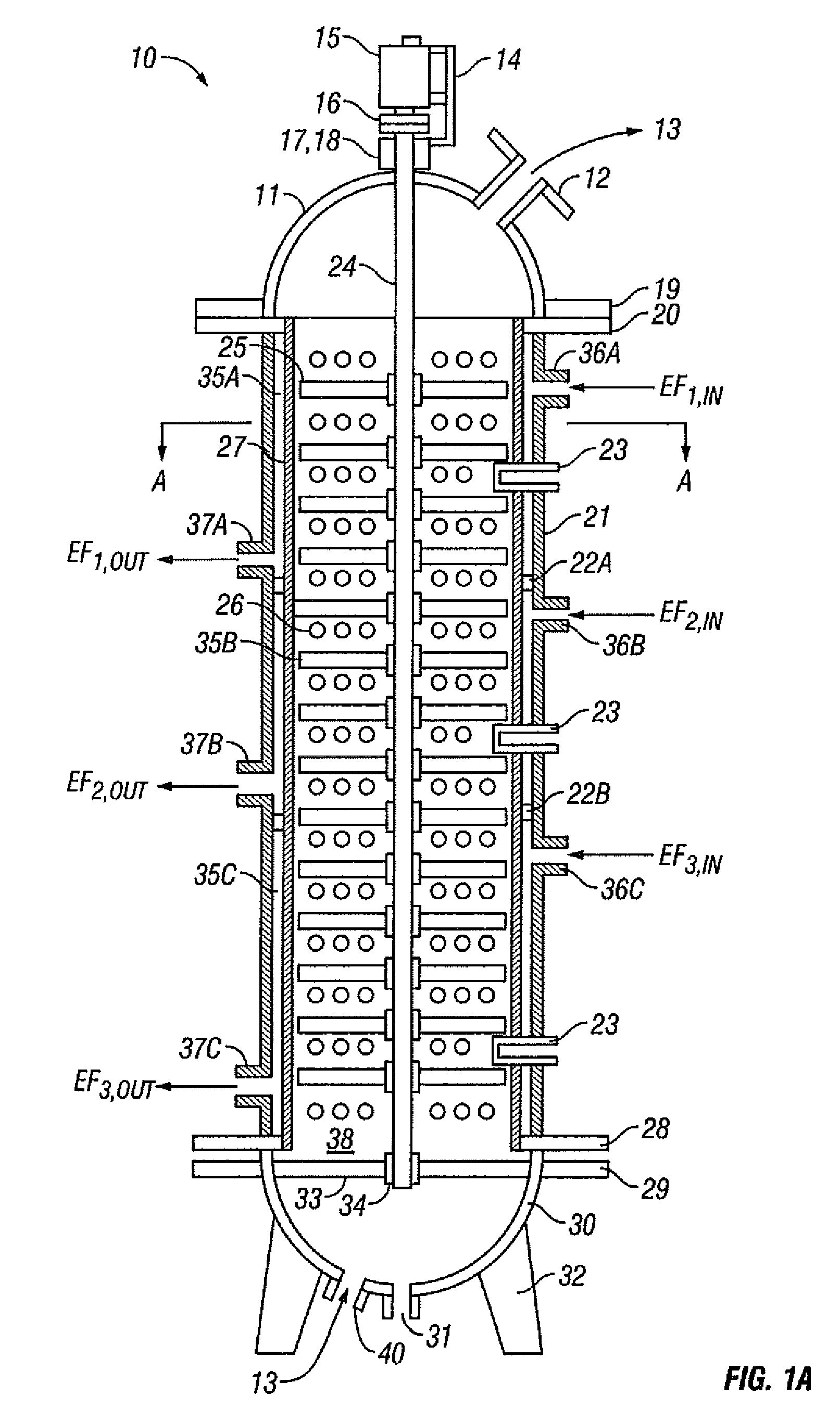
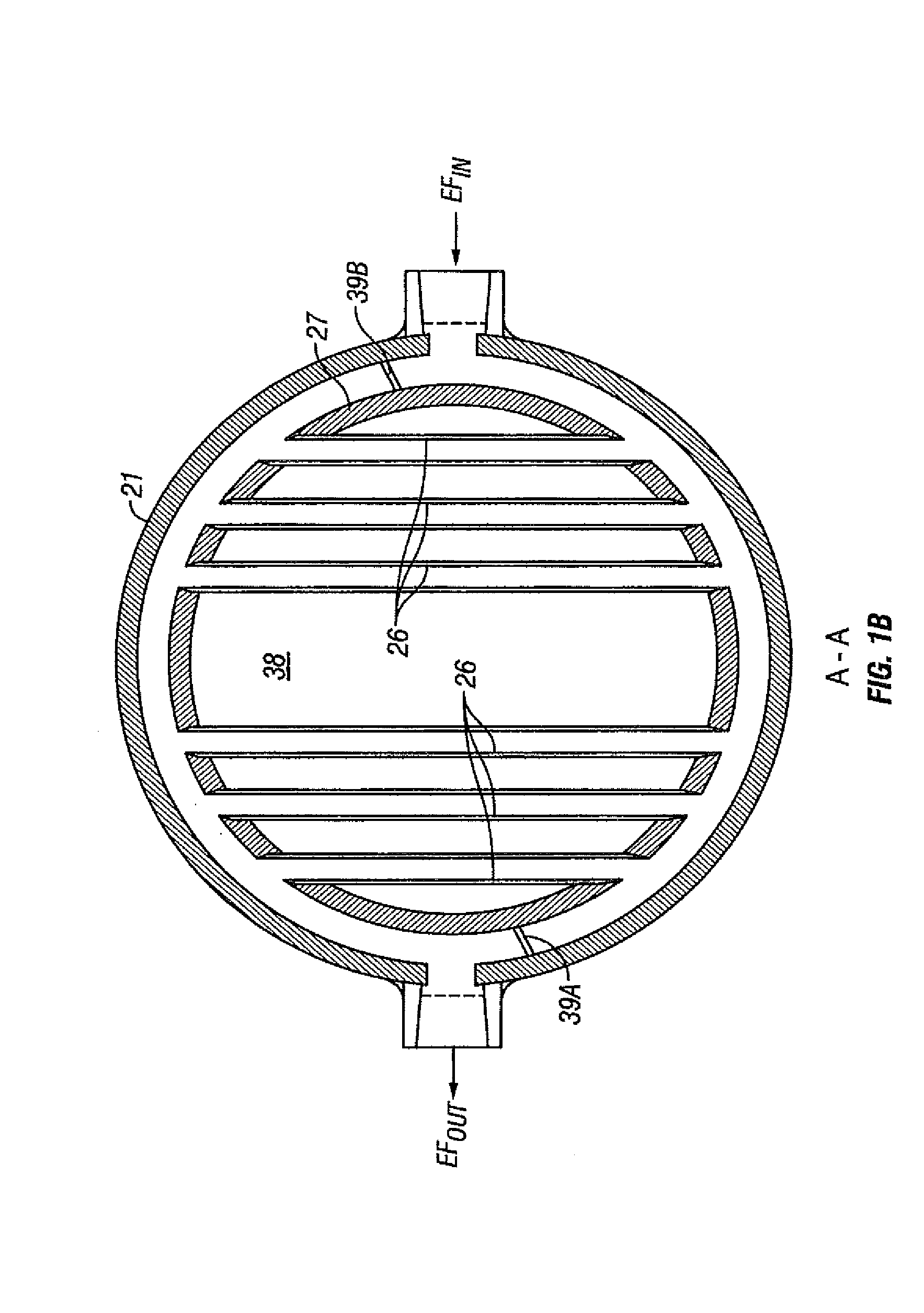
[0015]In one aspect, the invention is a plug flow reactor having an inner shell surrounded by outer shell and having at least one annular flow passage therebetween. This reactor may be used for any process that requires a plug flow reactor, but is especially desirable for those reactions that require an initial heating and then cooling, such as occurs in the polymerization of styrene and rubber modified styrene. The reactor of the invention is desirably efficient at removing heat and maintaining a plug flow as the reactants pass through the reactor.

[0016]Another advantage of the reactor is that it may be manufactured comparatively inexpensively. In some embodiments of the invention, the outer shell acts, in effect, as a common header for all of the heat exchanger tubes in a section of the plug flow reactor. This is a significant advantage over the prior reactors that required a separate flange to a heat transfer fluid source.

[0017]The reactor of the invention can be easily controlle...


PUM

PropertyMeasurementUnit
temperatureaaaaaaaaaa
compositionsaaaaaaaaaa
timeaaaaaaaaaa

Abstract

A plug flow reactor having an inner shell 27 surrounded by outer shell 21 and having at least one annular flow passage 35 therebetween can be used to prepare compositions, including polymers. The plug flow reactor also includes inlet port 36, an outlet port 37 and a plurality of exchanger tubes 26 wherein the exchanger tubes are in fluid communication to the at least one annular flow passage. Polystyrene and high impact polystyrene can be prepared using the reactor.

Description

BACKGROUND OF THE INVENTION[0001]1. Technical Field[0002]The invention relates to a plug flow reactor. The invention particularly relates to a plug flow reactor for use in preparing polystyrene and impact polystyrene.[0003]2. Background of the Art[0004]Exothermic processes for the production of compositions such as, for example, polystyrene are known. In these processes, the reactants are first heated to initiate the reaction, but then the reactants are cooled during the reaction. The capacity to cool the reactants is often a limiting process parameter.[0005]Such highly exothermic processes, unless carefully controlled, can cause the operation of reactors both to be hazardous and to lead to undesirable side reactions. For example, in the production of synthetic natural gas, run-away reactor conditions can lead to the depositing of coke and eventually plugging the equipment. Control of such reactors can be further complicated as a commercial reactors generally must handle reactant fe...

Claims


Application Information

Patent Timeline
31 Mar 2009
Publication
US7511101B2
IPC
C08F279/00; B01J19/24; F24H3/02; F28D7/00; F24H3/00; C07C1/00
CPC
B01F7/00291; B01F7/00633; B01F15/066; B01J19/18; F28D7/0066; F28D7/0091; B01J2219/00063; B01J2219/00081
Inventors
NGUYEN, THANH T.; REIMERS, JAY L.