Irradiated formation tool (IFT) apparatus and method

a technology of irradiation and formation tool, which is applied in the direction of instruments, nuclear radiation detection, measurement devices, etc., can solve the problems of uneven wall surface interference, poor detection effect, and inability to distinguish between oil and water phase of pore volume, and achieve accurate water saturation and high capture cross-section

Inactive Publication Date: 2009-03-31
NRC ENTERPRISES
View PDF12 Cites 22 Cited by
  • Summary
  • Abstract
  • Description
  • Claims
  • Application Information

AI Technical Summary

Benefits of technology

[0012]Surrounding the N-G detector, there is provided a sleeve or shield of selected rare earth material having a high capture cross-section for neutrons and characterized by having a significant thermal neutron induced capture gamma radiation energy response in the TLES part of the aggregate spectrum and having an insignificant capture gamma radiation response in the THES part of the aggregate spectrum. The selected material of the shield and the functionality of the shield are explained in U.S. Pat. No. 3,772,513 and other preferred embodiments.
[0013]By comparing the count rate of the THES with that of the TLES, the pore volume fluid is determined as to the presence or absence of hydrocarbons and an apparent sigma water (Σwa) is derived. By incorporating sigma water (Σwa) with that of the pore volume (Φ) determination from the ratio of the N-N detectors, a sigma log (Σlog) is generated with accurate water saturation for the corresponding earth formation. And, by comparing the count rate of the THES with the responses of the N-N detectors, earth formation matrix change is discerned.

Problems solved by technology

Also, differentiating between the oil and water phase of the pore volume has been questionable at best.
When running a logging instrument through an open wellbore, efficient movement of the instrument may be subject to the interference of uneven wall surfaces, such as when relatively unconsolidated formation material is washed away by drilling fluid or sloughs into the wellbore.
Additionally, these adverse wellbore conditions can cause the tools to become stuck in the wellbore resulting in costly retrieval or “fishing” operations for the operator of the well.
Unfortunately, the presence of steel casing eliminates or precludes most well logging tools to effectively measure the parameters of the earth formations within their design capability.

Method used


Image

  • Irradiated formation tool (IFT) apparatus and method
  • Irradiated formation tool (IFT) apparatus and method
  • Irradiated formation tool (IFT) apparatus and method

Examples


Embodiment Construction

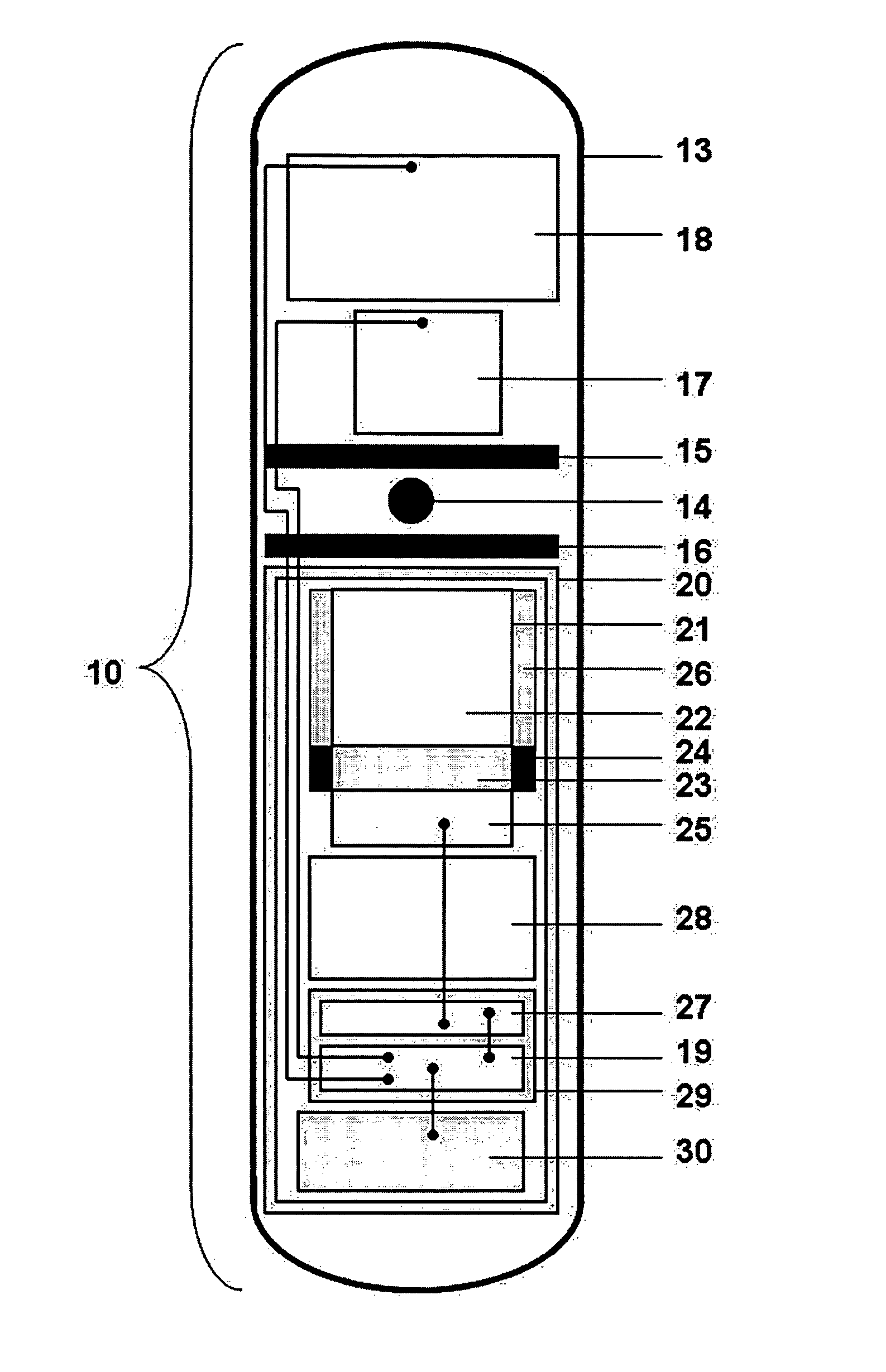
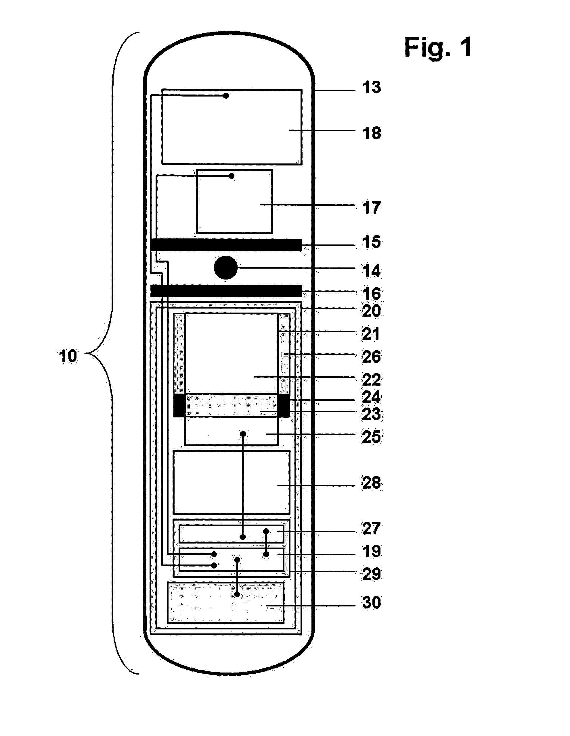
[0027]Turning now to FIG. 1, numeral 10 designates the well logging apparatus or tool in accordance with the present invention. An elongated housing 13 adapted for lowering into a borehole to a desired depth of a subterranean formation that is fluid tight and pressure resistant. Mounted inside the housing 13 above and below a neutron emitting source 14 are an upper neutron shield 15 and a lower neutron shield 16. The shields 15 and 16 may be composed of lead, tungsten, boron or a combination of one or more of these elements. These shields 15 and 16 prevent a direct path for emitted neutrons from the source 14 internally to the tool 10.

[0028]Mounted above the upper neutron shield 15 in the upper part of the housing 13 are two substantially identical Neutron-Neutron (N-N) detectors 17 and 18 having substantially identical function and operation. The arrangement of the two N-N detectors with respect to the distance from the neutron emitting source 14 designates the closest N-N detector...


PUM


Abstract

A well logging instrument that has a neutron source for irradiating earth formations traversing a borehole used in deriving useful information pertaining to said formations. Three detectors are mounted in a spaced-apart vertical relationship within a pressure-resistant housing. The detectors nearest and farthest from the neutron source detect thermal neutrons while the third detector from the neutron source detects a rare earth compensated aggregate capture gamma ray spectrum. By comparing the irradiated formations as detected by the three detectors, certain formation fluid, matrix, and pore volume parameters are derived. Also, by comparing the count rates of high and low energy ranges of the third detector in earth coal formation matrix, an ash volume is determined. From this value, a bulk density is derived from the corresponding earth coal formation.

Description

BACKGROUND OF THE INVENTION[0001]1. Field of the Invention[0002]The present invention relates generally to a method and apparatus for the determination of the nature of the earth formations by neutron well logging. More specifically the present invention concerns the use of dual spaced detectors in a logging instrument in association with a third detector in the logging instrument and comparative data processing for detecting a ratio derived porosity measurement for the investigation of porous reservoir rock and coal bed formations. Even more specifically, the present invention concerns the use of a logging instrument having two substantially identical detectors and a differing third detector that are arranged to facilitate running of the logging instrument within well casing for optimized logging speed and efficiency and for achieving efficient and accurate formation logging. The logging instrument employs neutron-neutron sensors and a neutron-gamma capture sensor and a signal proc...

Claims


Application Information

Patent Timeline
Patent Type & Authority Patents(United States)
IPC IPC(8): G01V5/10
CPCG01V5/104
Inventor BOTHNER, RONALD E.
Owner NRC ENTERPRISES
Why Eureka
Try Eureka