Systems and methods that mitigate contamination and modify surface characteristics during ion implantation processes through the introduction of gases

a technology of ion implantation and surface characteristics, applied in the field of ion implantation, can solve the problems of atomic or molecular contaminant particles entering the ion beam, degradation or failure of devices formed, etc., and achieve the effects of preventing or and reducing the risk of contamination

Active Publication Date: 2009-03-31
AXCELIS TECHNOLOGIES
View PDF15 Cites 5 Cited by
  • Summary
  • Abstract
  • Description
  • Claims
  • Application Information

AI Technical Summary

Benefits of technology

[0010]The present invention discloses methods and systems that mitigate contamination and / or modify surface characteristics during ion implantation processes by introduction of atmospheric or reactive gases during the ion implantation process. It has been discovered that these introduced gas(es) can prevent or mitigate contaminants from being implanted into target devices, such as silicon wafers by one or more mechanisms. While not intending to be confined by theory, it is assumed that one of the mechanisms is the formation of gaseous volatile compounds by the reactive gas, which interact with the contaminants at the target surface, whereby the volatile compounds are then removed by, for example, a cryogenic or turbo-molecular pump. Another mechanism involves the formation of a surface layer, such as a passivation layer, created by the presence of the reactive gas during ion implantation. The surface layer mitigates or prevents implanting of contaminants into underlying layers of the device.

Problems solved by technology

One problem that can occur during the ion implantation process is the unwanted introduction of atomic or molecular contaminant particles into the ion beam.
These particles can be undesirably implanted into, or deposited onto, one or more target wafers, resulting in degradation or failure of devices formed thereon.

Method used


Image

  • Systems and methods that mitigate contamination and modify surface characteristics during ion implantation processes through the introduction of gases
  • Systems and methods that mitigate contamination and modify surface characteristics during ion implantation processes through the introduction of gases
  • Systems and methods that mitigate contamination and modify surface characteristics during ion implantation processes through the introduction of gases

Examples


Embodiment Construction

[0019]The present invention will now be described with reference to the attached drawings, wherein like reference numerals are used to refer to like elements throughout. It will be appreciated by those skilled in the art that the invention is not limited to the exemplary implementations and aspects illustrated and described hereinafter.

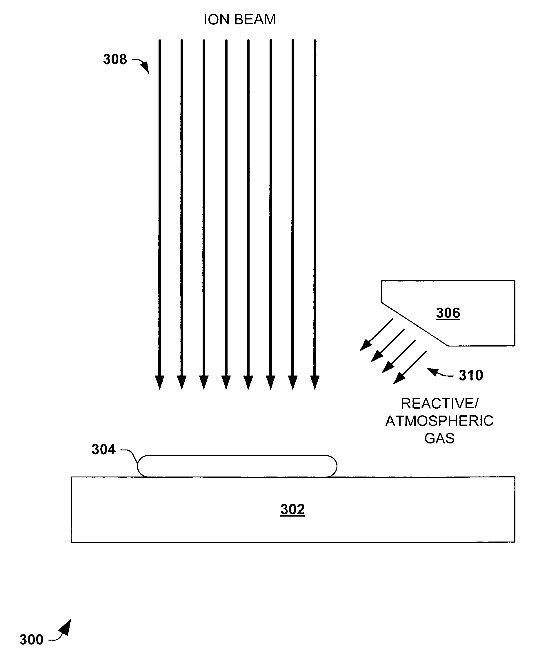
[0020]As semiconductor devices, such as sub-micron CMOS structures, become smaller and smaller, the ion implantation processes required to modify electrically active regions of semiconductor devices become shallower and more sensitive to the material properties in the surface and near surface regions of the semiconductor devices. Additionally, semiconductor devices are more sensitive to surface contamination from sputtered materials and absorbed gases present during implantation processes, particularly the concentration and distribution of contaminants within active device regions. Contaminants or particles can be implanted with the ion beam and negat...


PUM


Abstract

A contamination mitigation or surface modification system for ion implantation processes includes a gas source, a controller, a valve, and a process chamber. The gas source provides delivery of a gas, be it atmospheric or reactive, to the valve and is controlled by the controller. The valve is located on or about the process chamber and controllably adjusts flow rate and / or composition of the gas to the process chamber. The process chamber holds a target device, such as a target wafer and permits interaction of the gas with an ion beam to mitigate contamination of the target wafer and / or to modify the existing properties of the processing environment or target device to change a physical or chemical state or characteristic thereof. The controller selects and adjusts composition of the gas and flow rate according to contaminants present within the ion beam, or lack thereof, as well total or partial pressure analysis.

Description

RELATED APPLICATION[0001]This application claims the priority of U.S. Provisional Application Ser. No. 60 / 719,247, filed Sep. 21, 2005, entitled SYSTEMS AND METHODS THAT MITIGATE CONTAMINATION DURING ION IMPLANTATION PROCESSES THROUGH THE INTRODUCTION OF REACTIVE GASES.FIELD OF INVENTION[0002]The present invention relates generally to ion implantation typically employed in semiconductor device fabrication, and more particularly, to mitigating contamination and / or modifying the surface characteristics of target devices through the introduction of gases during ion implantation.BACKGROUND OF THE INVENTION[0003]Ion implantation is, typically, a physical process that is employed in semiconductor device fabrication to selectively implant dopant into semiconductor and / or wafer material. Thus, the act of implanting does not rely on a chemical interaction between a dopant and semiconductor material. For ion implantation, dopant atoms / molecules are ionized, accelerated, formed into a beam, an...

Claims


Application Information

Patent Timeline
Patent Type & Authority Patents(United States)
IPC IPC(8): H01J37/36
CPCH01J37/3171H01J2237/31705H01L21/26513H01J2237/022H01J2237/006H01L21/3065H01L21/265H01J37/317
Inventor REECE, RONALD N.KONDRATENKO, SERGUEI I.RA, GEUMJOOWAINWRIGHT, LOUIS P.CAI, GARY N.
Owner AXCELIS TECHNOLOGIES
Why Eureka
Try Eureka