Analog duty cycle replicating frequency converter for PWM signals

a frequency converter and duty cycle technology, applied in pulse generators, pulse manipulation, pulse techniques, etc., can solve the problems of reducing reducing the system cost, and relatively high clock frequencies to maintain the required translation accuracy, so as to reduce the overall system cost, reduce the system cost, and reduce the effect of cos

Active Publication Date: 2009-03-31
DELPHI TECH IP LTD
View PDF1 Cites 38 Cited by
  • Summary
  • Abstract
  • Description
  • Claims
  • Application Information

AI Technical Summary

Benefits of technology

[0004]This invention provides an analog, duty cycle replicating frequency converter capable of extracting duty cycle information from an input, pulse width modulated signal and generating an output pulse width modulated signal of the same duty cycle at a predetermined frequency, regardless of the frequency of the input signal. The converter of the invention uses analog signal processing techniques to allow implementation using application-specific integrated circuits (ASICs) fabricated in lower cost silicon processes. These dedicated ASICs can substantially reduce the system cost by reducing or eliminating the need for supply regulation and protection normally required for microprocessor based digital systems. Additionally, the overall system complexity is substantially reduced by use of a dedicated function control IC capable of driving the power switching devices of the motor control directly. The analog signal processing techniques comprising this invention are adaptable “on-the-fly” to varying input signal frequencies, allowing a single ASIC design to be widely applicable to various overall motor control systems where the duty-cycle information may be transmitted at different frequencies.

Problems solved by technology

But, while typical motor drive control signal switching frequencies are typically in the range of 20 kHz to 30 kHz, the transmission of control signals with frequency components in this range may be undesirable from the perspective of the electromagnetic noise from inadequately shielded conductors, for example in lengthy runs of control signal cabling between the control and the motor.
While this duty cycle replication at a higher frequency can be performed by digital signal sampling and processing techniques, the overhead of relatively high clock frequencies to maintain the required translation accuracy, along with the need for high level digital content, has typically required implementation using microprocessors and associated signal processing electronics.
These requirements all add cost to the overall system.

Method used


Image

  • Analog duty cycle replicating frequency converter for PWM signals
  • Analog duty cycle replicating frequency converter for PWM signals
  • Analog duty cycle replicating frequency converter for PWM signals

Examples


Embodiment Construction

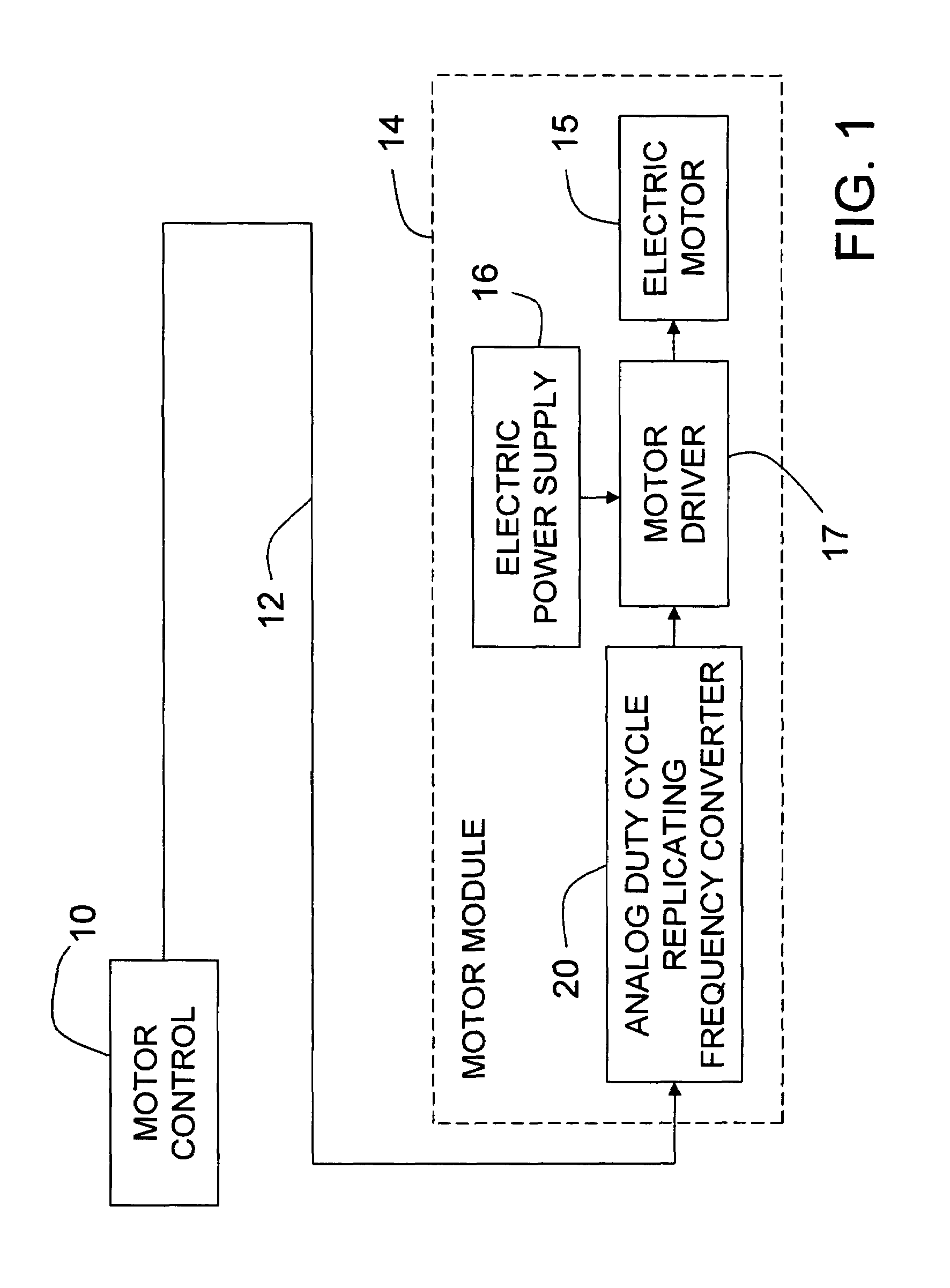
[0013]The preferred embodiment of the invention will be described in the environment of a motor control system, although it is not limited to such an environment. FIG. 1 is a block diagram of a motor control system in which a motor control 10 provides a control signal through an electrical control line 12 to a motor module 14. The details of motor control 10 are not significant to this invention, except that the control signal it produces on control line 12 has a pulse width modulated (PWM) electrical characteristic such as voltage with a comparatively low frequency, for example within a range of 100-400 Hz, so that control line 12 does not radiate undesirable electromagnetic interference to nearby electromagnetically susceptible devices. In one of many possible such motor control systems, motor control 10 may include an engine fuel control of a motor vehicle, while motor module 14 may be an electric motor driven fuel pump module in the vehicle fuel tank remotely located with respec...


PUM


Abstract

An analog, duty cycle replicating frequency converter extracts duty cycle information from an input, pulse width modulated signal and generates an output pulse width modulated signal of the same duty cycle at a different frequency without regard to the frequency of the input signal. It uses bipolar transistor based circuitry, adaptable to an application specific integrated circuit, to derive voltages representing the on-time and period durations of the input signal, convert these voltages to currents representing the logarithms thereof, generate a voltage representing the difference between the currents, exponentially convert the voltage to a current representing the duty cycle and control an oscillator to generate an output pulse width modulated signal at a predetermined frequency with the duty cycle of the input signal.

Description

TECHNICAL FIELD[0001]The technical field of this invention is duty cycle replicating frequency converters for pulse width modulated (PWM) signals.BACKGROUND OF THE INVENTION[0002]Many electronically controlled systems use pulse width modulated (PWM) control systems. For example, modern electric motor control systems utilize pulse width modulated control signals to switch the motor drive power switching devices. Such control enhances motor efficiencies and can easily be generated by digital control systems. But, while typical motor drive control signal switching frequencies are typically in the range of 20 kHz to 30 kHz, the transmission of control signals with frequency components in this range may be undesirable from the perspective of the electromagnetic noise from inadequately shielded conductors, for example in lengthy runs of control signal cabling between the control and the motor. Many operating environments, such as automotive systems, have stringent requirements for the sup...

Claims


Application Information

Patent Timeline
Patent Type & Authority Patents(United States)
IPC IPC(8): H03K3/017H03K5/04H03K7/08
CPCH02M5/297
Inventor KESLER, SCOTT B.
Owner DELPHI TECH IP LTD
Why Eureka
Try Eureka