Method for operating a furnace

a multi-burner, furnace technology, applied in the ignition of turbine/propulsion engines, combustion types, lighting and heating apparatus, etc., can solve the problems of difficult to find and complicated control of the fuel supply system, and achieve the effect of simplifying the safe operation of the combustion chamber close to the lean extinguishing limit and reducing the safety margin

Inactive Publication Date: 2009-04-07
ANSALDO ENERGIA IP UK LTD
View PDF18 Cites 17 Cited by
  • Summary
  • Abstract
  • Description
  • Claims
  • Application Information

AI Technical Summary

Benefits of technology

[0004]An object of the present invention is to provide an improved embodiment of an operating method of the above-mentioned type so that especially a safe operation of the combustion chamber close to the lean extinguishing limit is simplified or even made possible in the first place. Preferably, it should be possible to reduce the safety margin from the lean extinguishing limit that has been necessary so far.
[0006]The pressure pulsations can be detected in a conventional manner, which entails a comparison of a measured actual value to a predefined or adjustable setpoint, and which allows an appropriate adjustment of the fuel feed as a function of this setpoint-to-actual value comparison of the pressure pulsations. This feedback via the pressure pulsations translates into a closed-loop control circuit for the fuel feed to the burners. The operation of the gas turbines or the fuel feed to the burners is greatly simplified by the operating method according to the invention since, by taking into account the intensity or amplitude of the pressure pulsations, the boundary conditions repeatedly mentioned above that determine the distance of the combustion process to the mean extinguishing limit are automatically taken into account in the control system, without a need for their having to be explicitly monitored and / or having to be integrated into the control system for this purpose. It goes without saying that the operating method according to the invention markedly reduces the effort required to operate the gas turbine. Moreover, by properly selecting the setpoints of the pressure pulsations, the combustion chamber can be operated safely and yet very close to the lean extinguishing limit.
[0007]A particularly advantageous aspect of the operating method according to the invention is the fact that a modern combustion chamber is normally fitted with sensors to monitor the pressure pulsations anyway, so that these sensors can be employed to operate the gas turbine in the manner according to the invention, and consequently no additional costs are incurred for the instrumentation or for the implementation of the operating method according to the invention.
[0008]According to a particularly advantageous embodiment, when a predefined or adjustable maximum value of the pressure pulsations has been reached, the fuel feed to at least one burner of the combustion chamber is made richer by a predefined value. This maximum value of the pressure pulsations can be ascertained, for example, empirically, and it defines the smallest distance from the lean extinguishing limit at which stable operation of the combustion chamber can still be ensured. The stipulation of a certain value by which the fuel feed to the burner in question is to be made richer allows for a fast response of the control system and thus adherence to the smallest possible distance between the actual value and the setpoint of the pulsations.
[0009]In another embodiment, when a predefined or adjustable minimum value of the pressure pulsations has been reached, the fuel feed to at least one burner can be made leaner by a predefined value. In this embodiment, a maximum distance between the combustion reaction and the lean extinguishing limit is defined for the operation of the combustion chamber, and this maximum distance must not be exceeded. This measure ensures that the smallest possible distance from the lean extinguishing limit is maintained at all times, which leads to low emissions of pollutants.

Problems solved by technology

The control of the fuel supply system is particularly complex when the boundary conditions taken into account vary.
Since the individual boundary conditions affect the stability of the combustion procedure in different ways, it is not always possible to find a setting for the fuel feed that allows a stable operation of the individual burners close to the lean extinguishing limit.

Method used


Image

  • Method for operating a furnace
  • Method for operating a furnace
  • Method for operating a furnace

Examples


Embodiment Construction

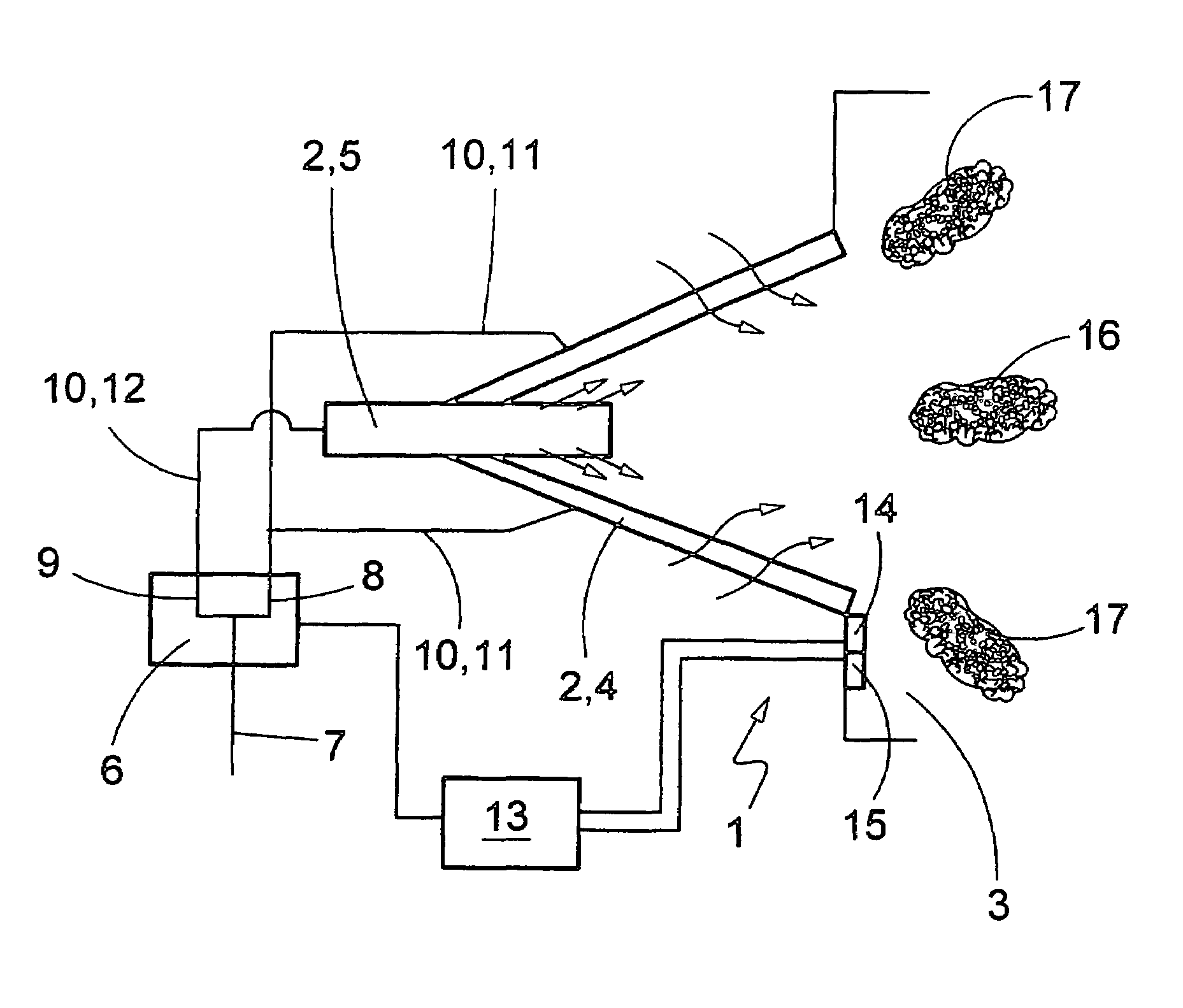
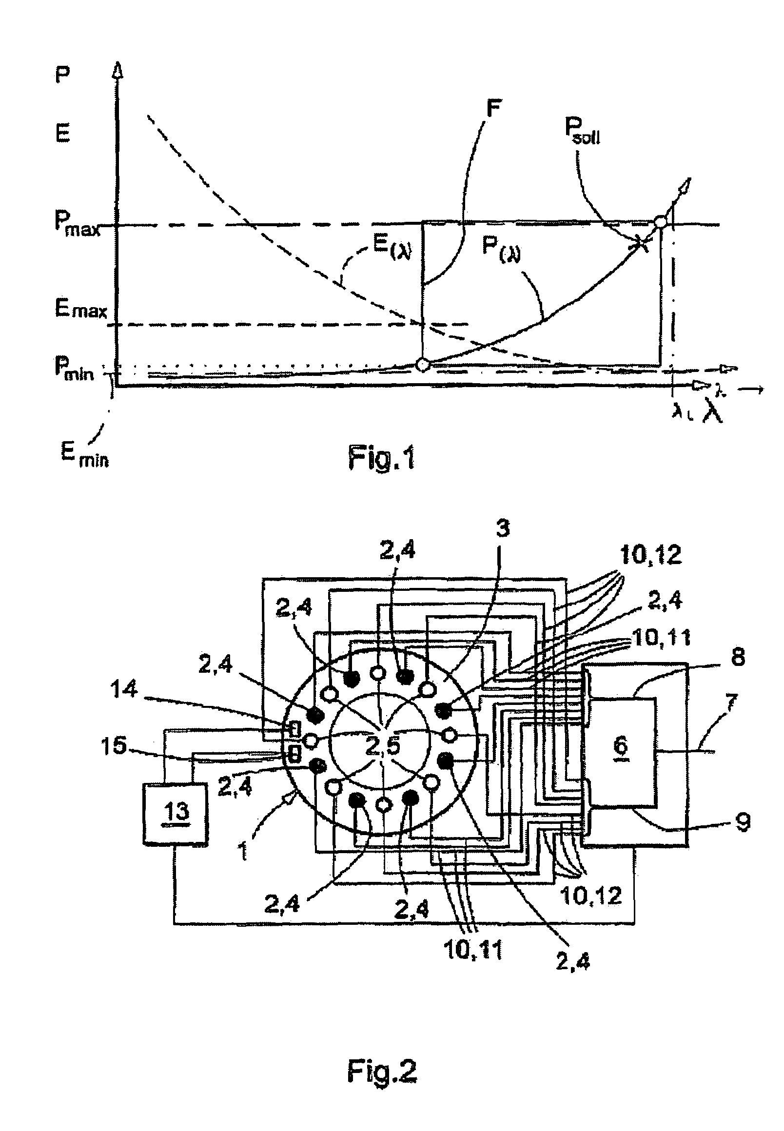
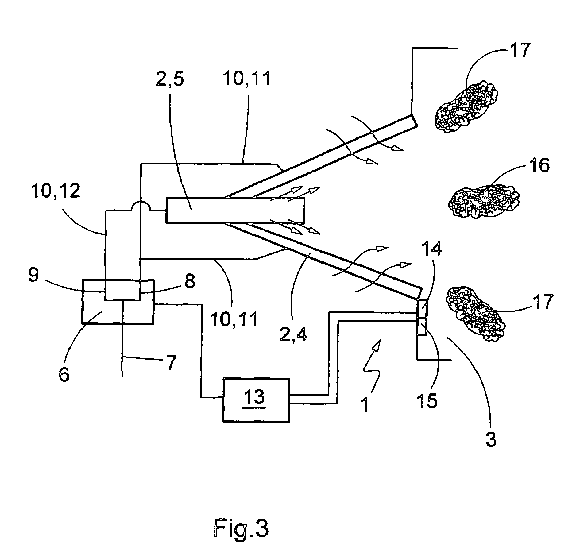
[0016]According to FIG. 2, a combustion chamber 1 of a furnace (not shown here) is equipped with several burners 2, as a result of which a multi-burner system is created. The burners 2 are arranged here on the inlet side, for example, of an annular combustion space 3 of the combustion chamber 1. In the case of a furnace configured as a gas turbine, especially of a power plant, a compressor (not shown here) is generally located upstream from the combustion chamber 1, while the actual turbine (not shown here) is located downstream from the combustion chamber 1.

[0017]The burners 2 are divided into two groups, namely, a main group and a secondary group. The burners 2 of the main group are symbolized by solid circles here and will be referred to below as main burners 4. In contrast, the burners 2 of the secondary group are symbolized by empty circles and will be referred to below as secondary burners 5. Normally, the main burners 4 are operated with a richer feed than the secondary burne...


PUM


Abstract

A method for operating a furnace with a multi-burner system for generating a hot gas is provided. The furnace has a combustion chamber with a plurality of burners, each having a fuel feed. The method includes regulating a first fuel feed to at least one of the plurality of burners as a function of pressure pulsations that occur in the combustion chamber so as to achieve a steady operation of the furnace. The multi-burner system may be a gas turbine, preferably of a power plant.

Description

BACKGROUND[0001]The present invention relates to a method for operating a furnace with a multi-burner system for generating hot gas, particularly a gas turbine, preferably of a power plant.[0002]A furnace, for example, a gas turbine, normally has a combustion chamber with multiple burners. Moreover, it is often the case that a fuel supply system is provided by means of which fuel is fed to the burners.[0003]With an eye towards the ever more stringent regulations pertaining to the mandatory limit values for the emission of pollutants, efforts are made to operate the burners under the leanest conditions possible, that is to say, with a marked excess of oxidant, usually air. Such lean operation is able to considerably reduce particularly the formation of especially toxic NOx emissions. The lean combustion concurrently causes the combustion reaction to approach its lean extinguishing limit. Therefore, in order to keep pollutant emissions to a minimum, efforts are geared towards operatin...

Claims


Application Information

Patent Timeline
Patent Type & Authority Patents(United States)
IPC IPC(8): F23N1/00F02C7/228F23R3/28F23M20/00
CPCF23R3/34F23R3/50F23C2900/06042F23N5/16F23N2041/20F23R2900/00013F23N2241/20
Inventor GARAY, MAURICIOGUIDATI, GIANFRANCO LPENNELL, DOUGLAS A.REISS, FRANK
Owner ANSALDO ENERGIA IP UK LTD
Why Eureka
Try Eureka