Valve gear of internal combustion engine

a technology of internal combustion engine and valve gear, which is applied in the direction of non-mechanical valves, valve drives, machines/engines, etc., can solve the problems of the rotation region in which the desired valve gear characteristic cannot be obtained, and achieve the effect of high control accuracy of the valve gear characteristi

Inactive Publication Date: 2009-04-07
TOYOTA JIDOSHA KK
View PDF13 Cites 10 Cited by
  • Summary
  • Abstract
  • Description
  • Claims
  • Application Information

AI Technical Summary

Benefits of technology

[0004]Accordingly, one object of the present invention is to provide a valve gear of an internal combustion engine which can maintain a high control accuracy of a valve gear characteristic of a valve regardless of a change of an engine rotation number.
[0007]On the other hand, the inertia torque of the cam shaft is increased in proportion to a square of the rotating speed, and when the cam shaft is rotated at a high speed, an influence of the inertia torque is relatively increased, and the cam shaft torque becomes maximum at a position at which the acceleration of the valve becomes maximum. When the lift speed is increased to the maximum for a short time from the lift start, the acceleration of the valve is increased. Accordingly, the cam shaft torque at the time of the high rotation of the cam shaft is significantly increased. Therefore, in order to reduce the cam shaft torque in the high rotation region, it is necessary to design the profile of the cam such that the maximum acceleration of the valve becomes small.
[0010]In the valve gear in accordance with the above aspect of the present invention, the electric motor control device may control the electric motor such that when the rotation number of the internal combustion engine is low, the speed of the cam in predetermined sections after starting the lift of the valve and before finishing the lift becomes higher than the speed of the cam in a section between the predetermined sections, and when the rotation number of the internal combustion engine is high, the cam is rotated at a constant speed during the lift of the valve. In this case, in the low speed region, it is possible to apply the maximum speed to the valve at the stage where the lift amount of the valve is small, thereby restricting the valve spring torque. In the high rotation region, it is possible to lighten a load for controlling the electric motor at the time of the high rotation by rotating the cam at a constant speed, thereby preventing the deterioration of the motion control of the valve due to a lack of response of the control. In the above aspect, the electric motor control device may control the electric motor such that a difference of the rotating speed of the cam is reduced between the predetermined sections and the intermediate section in accordance with an increase of the rotation number of the internal combustion engine, by changing the speed in the above manner. In this case, it is possible to smoothly change the acceleration characteristic of the valve with respect to the change of the rotation number of the internal combustion engine, thereby preventing drivability from being deteriorated.
[0011]Further, in the valve gear in accordance with the above aspect of the present invention, the electric motor control device may control the electric motor such that when the rotation number of the internal combustion engine is low, the cam is rotated at a constant speed during the lift, and when the rotation number of the internal combustion engine is high, the speed of the cam in predetermined sections after starting the lift of the valve and before finishing the lift becomes lower than the speed of the cam in an intermediate section between the predetermined sections. In this case, it is possible to restrict the inertia torque by reducing the maximum acceleration of the valve in the high speed region. In the above aspect, the electric motor control device may control the electric motor such that a difference of the rotating speed of the cam is increased between the predetermined sections and the intermediate section in accordance with an increase of the rotation number of the internal combustion engine. In this case, it is possible to smoothly change the acceleration characteristic of the valve with respect to the change of the speed of the internal combustion engine, by changing the speed in the above manner, thereby preventing drivability from being deteriorated.

Problems solved by technology

However, the cam shaft torque is fluctuated in correspondence to a rotation number (a rotating speed) of the engine, and there is a possibility that a rotation region in which a desired valve gear characteristic cannot be obtained is generated due to the fluctuation.

Method used


Image

  • Valve gear of internal combustion engine
  • Valve gear of internal combustion engine
  • Valve gear of internal combustion engine

Examples


first embodiment

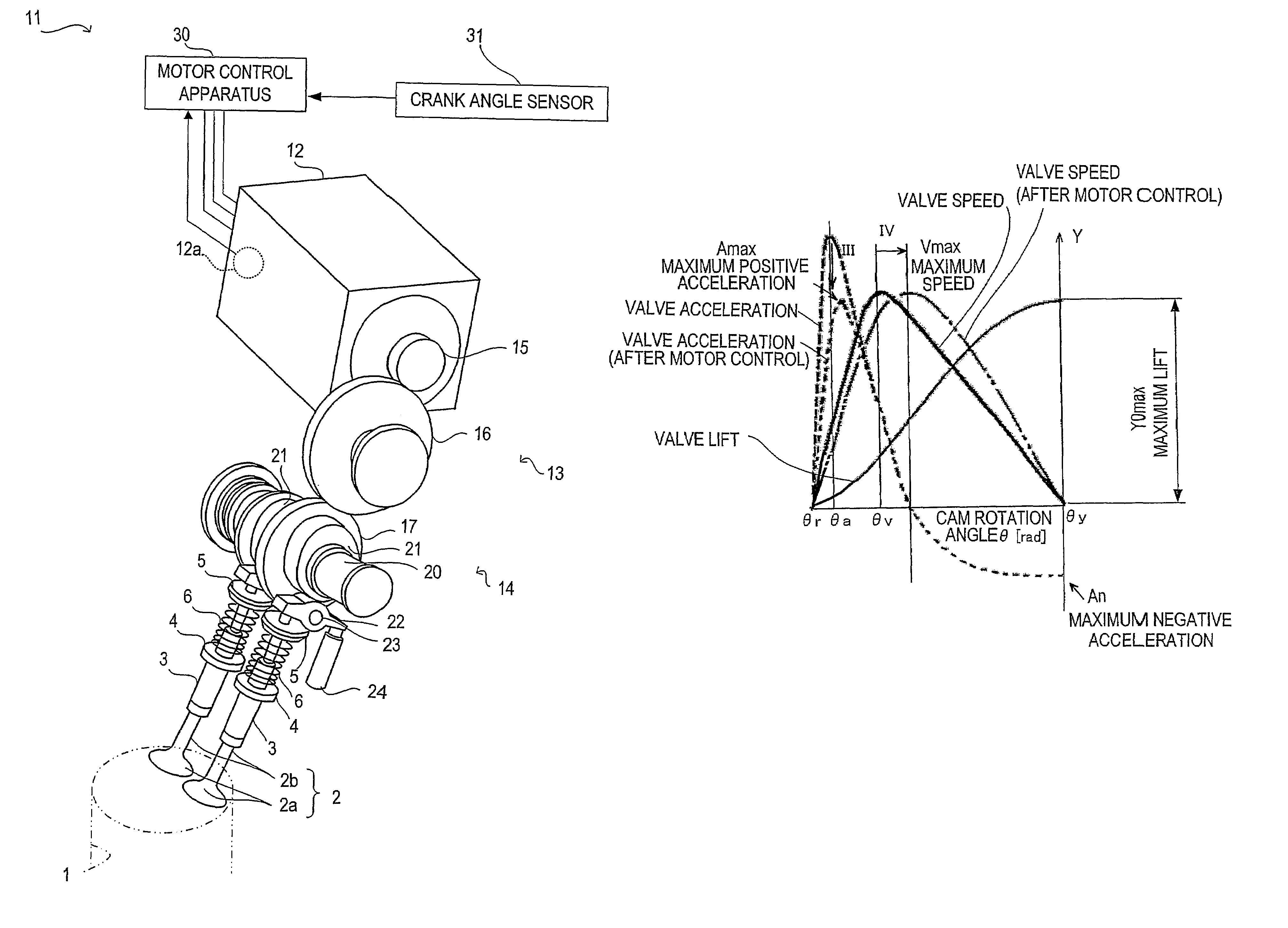
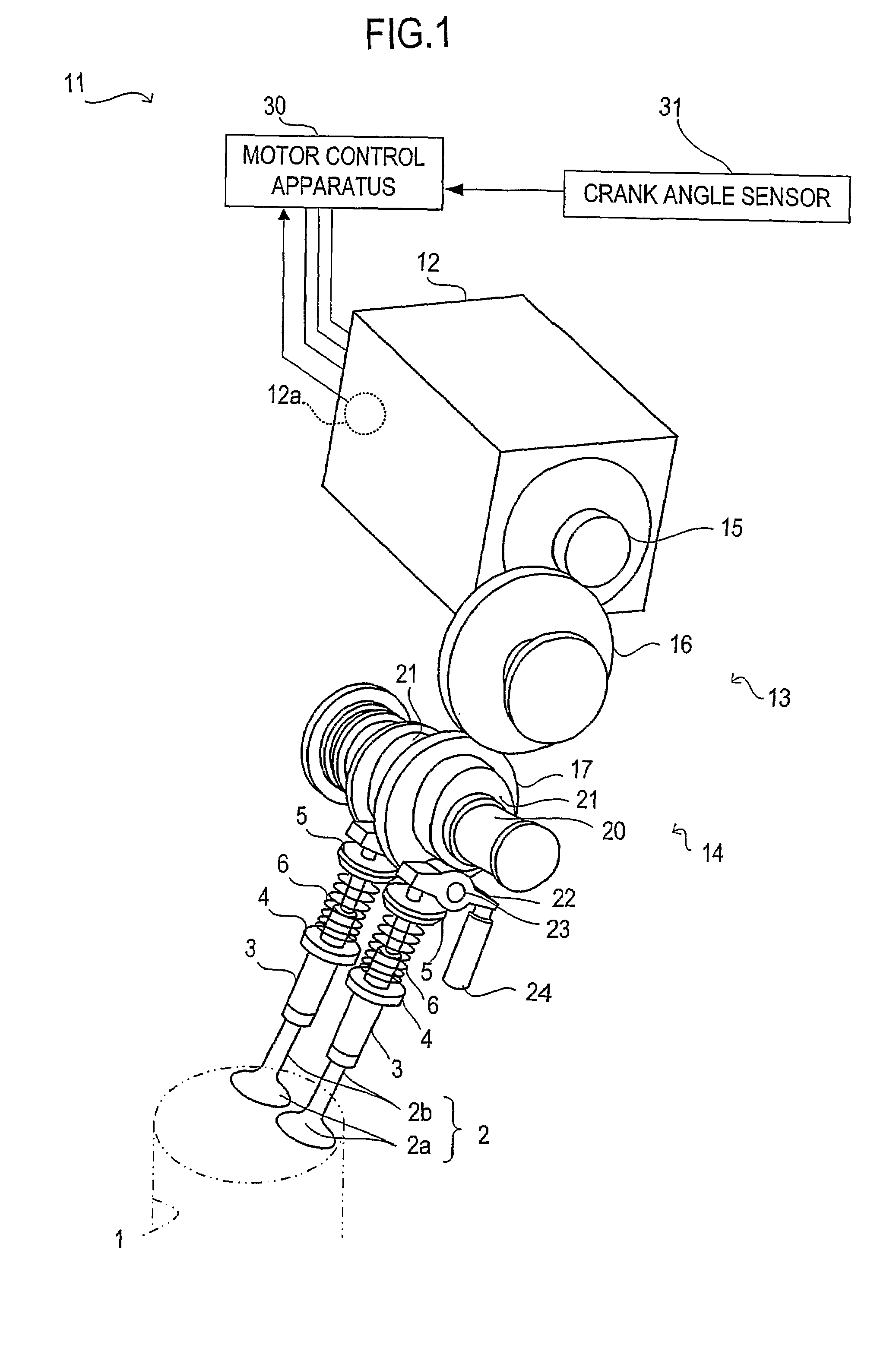
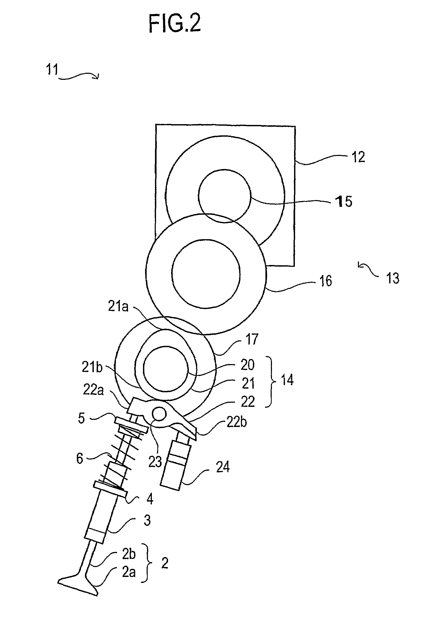
[0022]FIG. 1 shows an embodiment in which a valve gear in accordance with the present invention is applied so as to drive an intake valve of a reciprocal type internal combustion engine. In this embodiment, two intake valves 2 are provided in each of cylinders 1 (only one is illustrated in the drawing) provided in the internal combustion engine, and the intake valve 2 is driven so as to be opened and closed by a valve gear 11 provided in each of the cylinders 1. As is well known, the intake valve 2 has a valve head 2a and a stem 2b. The stem 2b is passed through a sleeve 3 fixed to a cylinder head (not shown), whereby the intake valve 2 is slidably guided in an axial direction of the stem 2b. A valve spring 6 is arranged between a flange 4 protruding from the sleeve 3 and a valve spring retainer 5 attached to the stem 2b in a compressed state, and the intake valve 2 is energized in a direction of being in close contact with a valve seat (not shown), that is, to an upper side in FIG....

second embodiment

[0035]In the first embodiment, the profile of the cam 21 is designed while giving priority to the reduction of the inertia torque in the high rotation region, however, the present invention may be realized on the opposite aspect. One embodiment thereof will be shown in FIGS. 6 to 8.

[0036]In this embodiment, first on the assumption that giving priority to the restriction of the valve spring torque in the low rotation region, the profile of the cam 21 is designed such that the maximum speed cam angle θv giving the maximum lift speed Vmax becomes as early as possible. In this case, if the cam 21 is driven at the basic speed regardless of the engine rotation number, the maximum acceleration Amax just after starting the lift and just before finishing the lift is increased in proportion to a square of the increase of the engine rotation number, and the inertia torque in the high rotation region is significantly enlarged. In order to avoid this, the rotating speed of the motor 12 is change...


PUM


Abstract

There is provided a valve gear (11) with a motor (12), a cam mechanism (14) which converts a rotational motion of the motor (12) into a linear motion of an intake valve (2) by a cam (21), and a motor control apparatus (30) which controls the motor (12) such that an acceleration characteristic during a lift of the intake valve (2) changes in correspondence to a rotation number of an internal combustion engine.

Description

TECHNICAL FIELD[0001]The present invention relates to a valve gear driving an intake valve or an exhaust valve of an internal combustion engine.BACKGROUND ART[0002]As this kind of valve gear, there has been known a valve gear which opens and closes the intake valve by rotating a cam shaft of the internal combustion engine by a stepping motor (Japanese Patent Application Laid-Open (JP-A) No. 8-177536). In addition, there is JP-A No. 59-68509 as a prior technical document relevant to the present invention.[0003]A cam shaft torque caused by a valve spring and inertia is applied to the cam shaft as a resistance against the rotation. However, the cam shaft torque is fluctuated in correspondence to a rotation number (a rotating speed) of the engine, and there is a possibility that a rotation region in which a desired valve gear characteristic cannot be obtained is generated due to the fluctuation.DISCLOSURE OF THE INVENTION[0004]Accordingly, one object of the present invention is to provi...

Claims


Application Information

Patent Timeline
Patent Type & Authority Patents(United States)
IPC IPC(8): F01L1/34F01L1/04F01L1/047F01L1/08F01L9/20F01L9/22F01L13/00F02D13/02
CPCF01L1/04F01L1/047F01L1/08F01L13/00F01L9/04Y10T74/2107F01L2009/0411F01L9/22F01L9/20
Inventor EZAKI, SHUICHIASADA, TOSHIAKITSUJI, KIMITOSHIKUSAKA, YASUSHI
Owner TOYOTA JIDOSHA KK
Why Eureka
Try Eureka