Ballistic missile interceptor guidance by acceleration relative to line-of-sight

a ballistic missile and trajectory technology, applied in direction controllers, target-seeking control, instruments, etc., can solve the problems of increasing the likelihood of damage to the target, unable to place intercept reliance on the destructive power of explosive warheads, and failure of kill vehicles to intercept their test targets

Inactive Publication Date: 2009-04-07
LOCKHEED MARTIN CORP
View PDF18 Cites 16 Cited by
  • Summary
  • Abstract
  • Description
  • Claims
  • Application Information

AI Technical Summary

Benefits of technology

[0013]In a further mode of this method, the step of applying the commanded missile thrust vector for control of the thrust of the mis

Problems solved by technology

Such antiaircraft artillery would seldom result in the actual striking of an aircraft with the shell, but relied on the fragments from the explosion of the shell to damage or destroy the aircraft.
Artillery shells, whether land-based, naval, or airborne, used explosives to increase the likelihood of damage to the target even in the case of a near miss.
With the emergence of ballistic threat missiles, intercept reliance could not be placed on the destructive power of an explosive warhead.
One may readily understand that many problems arise in the control and guidance of the kill vehicle under such conditio

Method used


Image

  • Ballistic missile interceptor guidance by acceleration relative to line-of-sight
  • Ballistic missile interceptor guidance by acceleration relative to line-of-sight
  • Ballistic missile interceptor guidance by acceleration relative to line-of-sight

Examples


Embodiment Construction

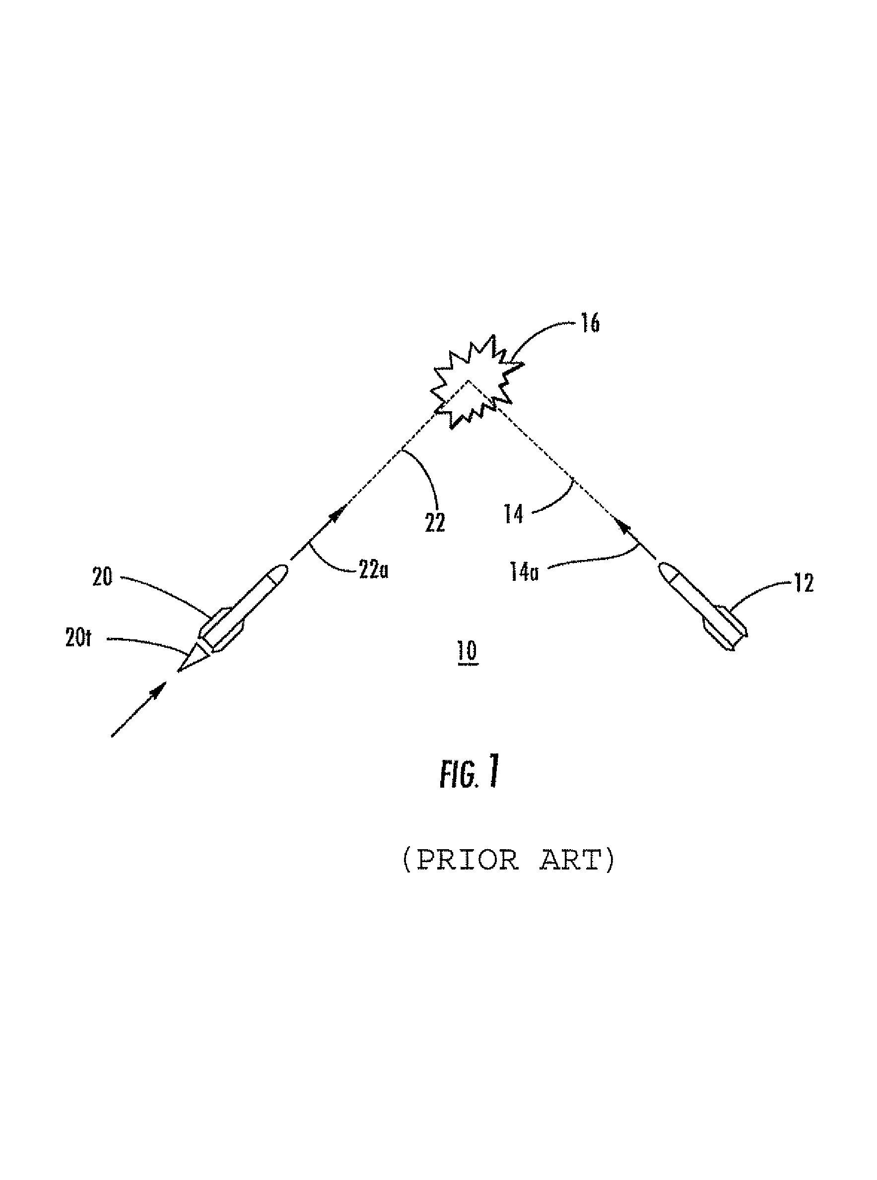
[0019]FIG. 1 illustrates a prior art guidance arrangement 10 in which a target vehicle 12 moves in a ballistic path 14 in the direction of arrow 14a toward a predicted intercept point 16. An interceptor vehicle or missile 20 generates thrust 20t in a direction which causes acceleration of the interceptor vehicle 20 along a path illustrated as 22, in a direction indicated by arrow 22a, toward the predicted intercept point 16. As mentioned, variables that are required for an intercept but are difficult to account for include the rocket engine impulse and the mass of the intercept vehicle.

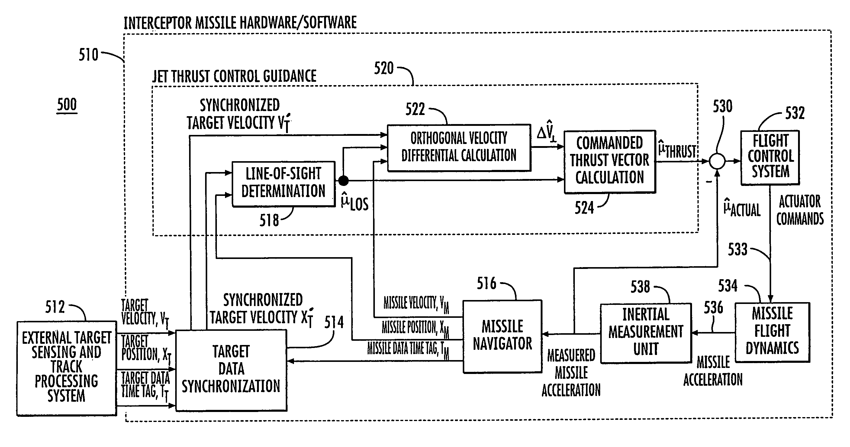
[0020]According to an aspect of the invention, a “Jet Thrust Control” (JTC) intercept vehicle or missile guidance control algorithm operates by assuming, before rocket motor ignition of the intercept vehicle, that the missile-heading vector is contained within some bound, but that the intercept vehicle and the ballistic target vehicle are not on a collision course. There is therefore a finite or non-z...


PUM


Abstract

A method for guiding an intercept vehicle to intercept a ballistic target includes conceptual setup of a line-of-sight (LOS) extending between the vehicles. The interceptor is accelerated in a direction perpendicular to the LOS until its velocity in that direction equals that of the target. At this time, the thrust of the interceptor accelerates it along the line-of-sight, thereby guaranteeing an intercept.

Description

GOVERNMENTAL INTEREST[0001]This invention was made with government support under Contract / Grant Aegis BMD N00024-98-C-5297. The United States Government has a non-exclusive, non-transferable, paid-up license in this invention.FIELD OF THE INVENTION[0002]This invention relates to vehicle guidance systems, and more particularly to such guidance systems that are intended to intersect a vehicle, such as an explosive or kinetic kill vehicle, with a moving target.BACKGROUND OF THE INVENTION[0003]A great deal of attention has been given to the issues relating to missile guidance for destroying stationary or moving targets. During World War II, antiaircraft cannon were operated in a manner that attempted to estimate the future location of an aircraft at the time that a shell would arrive at its altitude and range, and fired at the estimated location. Such antiaircraft artillery would seldom result in the actual striking of an aircraft with the shell, but relied on the fragments from the exp...

Claims


Application Information

Patent Timeline
IPC IPC(8): F41G7/00F42B15/01F42B15/00
CPCF41G7/30G05D1/12F42B15/01
Inventor MAVROUDAKIS, PETER J.BOKA, JEFFREY B.CORSO, JOSEPH T.
Owner LOCKHEED MARTIN CORP
Why Eureka
Try Eureka