One way valve

a one-way valve and valve body technology, applied in the direction of valve operating means/releasing devices, functional valve types, containers, etc., can solve problems such as performance halting

Inactive Publication Date: 2009-04-07
SU FU LONG
View PDF28 Cites 28 Cited by
  • Summary
  • Abstract
  • Description
  • Claims
  • Application Information

AI Technical Summary

Benefits of technology

[0025]5. Four components of the configuration structure are simple, easy to produce, and cost-efficient.
[0027]Projected annular ring (16) formed below the alignment hole (13) of aforesaid valve trough (12) is in connection with the air deflectors (15), the height of the annular ring (16) is lower than the air deflectors (15) to keep the alignment hole (15) from intruding by fallen portion of the sealed bag.
[0031]Stop device (3) is a buffer spring, which can exert a larger elastic force to the diaphragm (2) to achieve a preferred airtight effect.

Problems solved by technology

Otherwise, when air-expelled in the sealed bag, the fallen lower bag portion may be absorbed and intruded into the air pores, the performance comes to a halt.

Method used


Image

  • One way valve
  • One way valve
  • One way valve

Examples


first embodiment

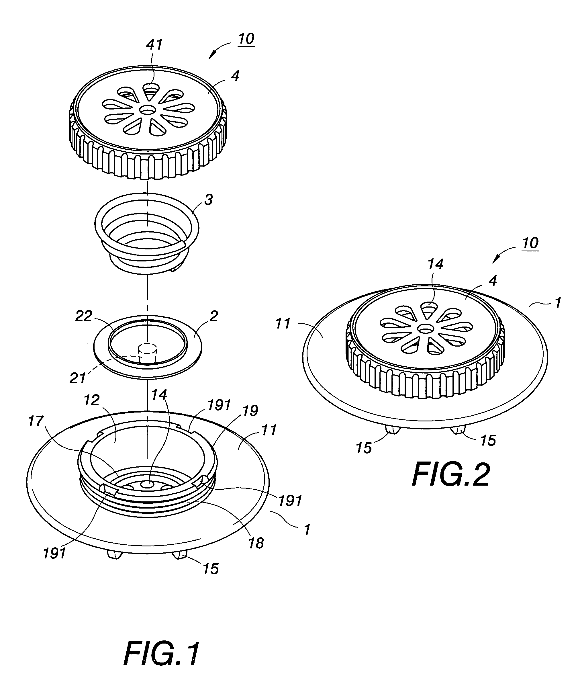
[0054]Referring to FIG. 1, an exploded view of the first embodiment of the present invention is illustrated. One-way valve (10) comprises a valve seat (1), a diaphragm (2) mounted inside the valve seat, the diaphragm (2) is in linear contact with a projected annular ring (17), a stop device (3) props against the diaphragm (2), a valve cap (4) screwed to the valve seat covers over a buffer spring (3). After combination, an assembled view is illustrated as shown in FIG. 2.

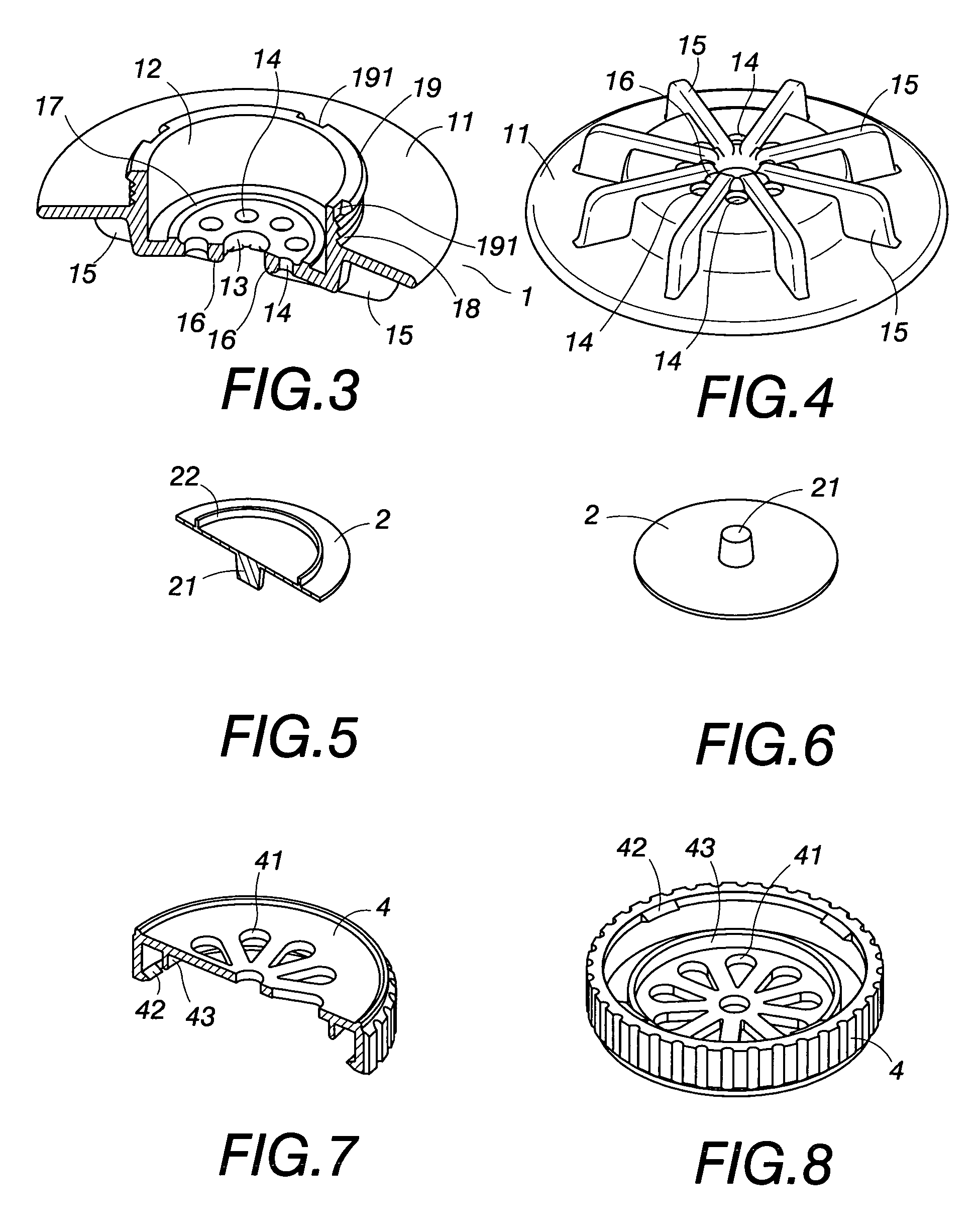
[0055]Aforesaid valve seat (1), whose structure is illustrated in FIGS. 3 and 4. Valve seat (1) has a valve trough (12) with an opening formed at a first end, a plate (11) extended radially outwardly from a circumference of the opening and secured to a sealed bag, a base having a central alignment hole (13) formed at a second end of the valve trough (12), the central alignment hole (13) is surrounded by a plurality of air pores (14) and a projected annular ring (17). The valve trough (12) has outer threads (18) forme...

second embodiment

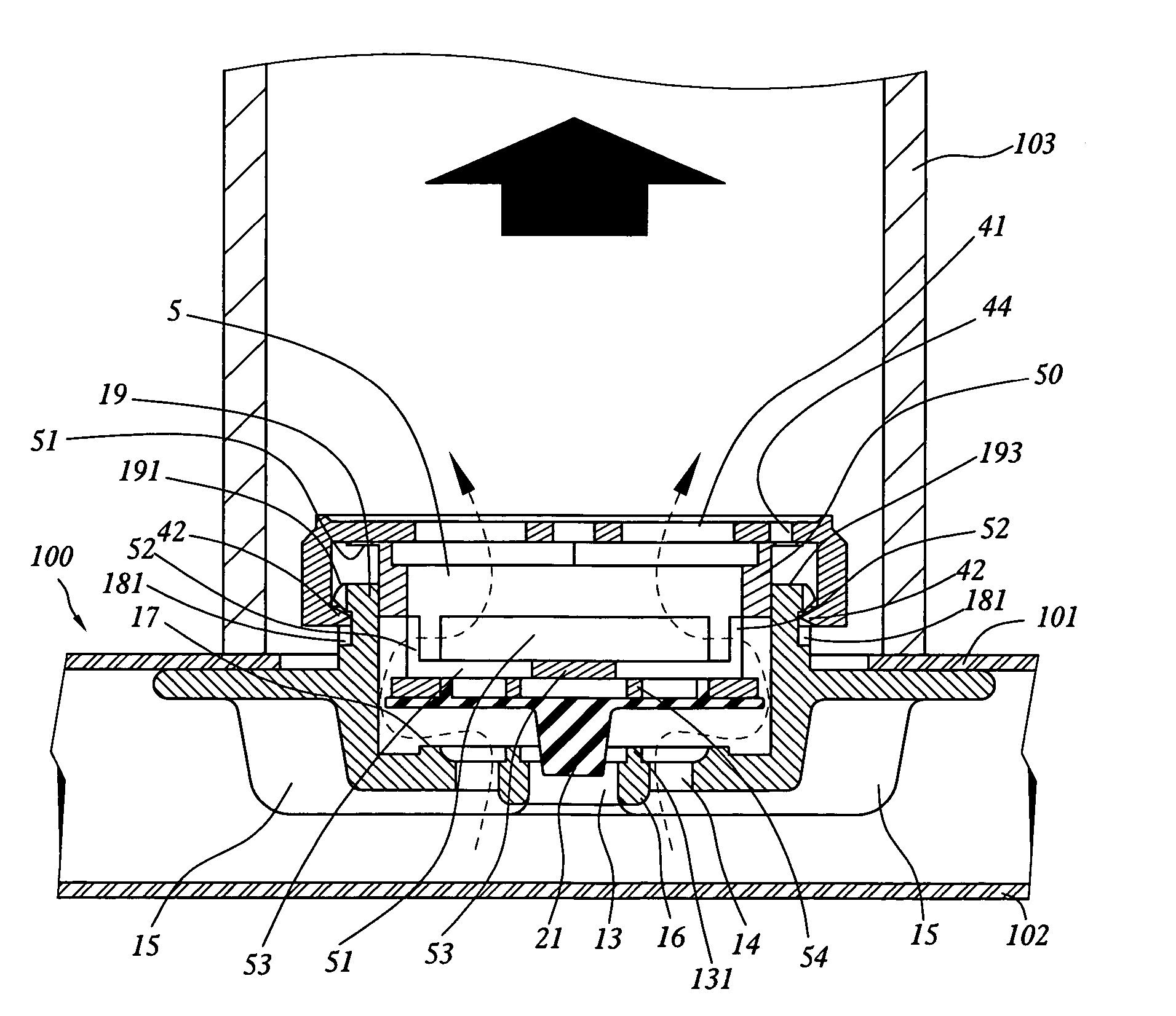
[0067]Referring to FIGS. 16 and 17, an exploded view and an assembled view of the second embodiment are illustrated. The second embodiment has a stop device (5) that is different from the first embodiment. The stop device (5) is made of a rigid, transparent, plastic compressed seat. Configuration structure of the stop device (5) is a truncated pipe (50) with an outer diameter smaller than the inner diameter of the valve trough (12). An annular lip (51) is extended radially outwardly from a top opening of the truncated pipe (50) to prop up the valve cap (4), a bottom end of the truncated pipe (50) props against the diaphragm (2). A projected annular ring (22) formed on a top of the diaphragm (2) is led into the bottom opening of the stop device (5) in position (Please refer to FIG. 18), an enhanced rib (53) in the shape of cross is formed inside the bottom opening of the stop device (5). A plurality of hollowed out troughs (52) formed around a circumference of the truncated pipe (50)...


PUM


Abstract

The present invention is to provide one-way valve of a sealed bag to expel the dead air out from the bag with a preferred air-tight effect. The one-way valve comprises a valve seat, a diaphragm mounted inside the valve seat, the diaphragm is also in linear contact with a projected annular ring, a stop device pressed on the diaphragm, a valve cap screwed to the valve seat and pressed the stop device. Said valve cap has hooks adapted to apertures of the seat, thus keep the cap on the seat not to be separated from thereof. Moving upward or downward the valve cap, the stop device can be controlled to press onto the diaphragm tightly or become loose. An airtight effect is achieved with a pressure exerted between the stop device and the annular ring. Or one-way valve can expel the dead air through the air pores under diaphragm.

Description

FIELD OF THE INVENTION[0001]The present invention is related to one-way valve of a sealed receiving bag. By means of an atmospheric pressure, it expels the dead air out of the bag without flowing back, also being suitable for preventing the fluid from flowing back thereto.BACKGROUND OF THE INVENTION[0002]Vacuum cleaners applied to expel the air from sealed bag, may reduce the bulky, fluffy volume of the received objects. Being a well-known technique to store the objects, such as clothes, quilts, occupied space can be reduced so as to inhibit bacteria growth. In practice, a valve is applied to expel the dead air from the bag without flowing back thereto. Thus one-way valve plays a role when using a sealed bag for receiving objects. About the structure of one-way valve, we can see five US patent documents about the one way valve as following: 1. U.S. Pat. No. 6,604,634 entitled “receiving bag with enhanced airtight effect” issued to the inventor of the present invention Fu-Long Su on ...

Claims


Application Information

Patent Timeline
Patent Type & Authority Patents(United States)
IPC IPC(8): F16K15/20
CPCB65D31/14B65D81/2038F16K15/028F16K24/04Y10T137/784
Inventor SU, FU-LONG
Owner SU FU LONG
Why Eureka
Try Eureka