

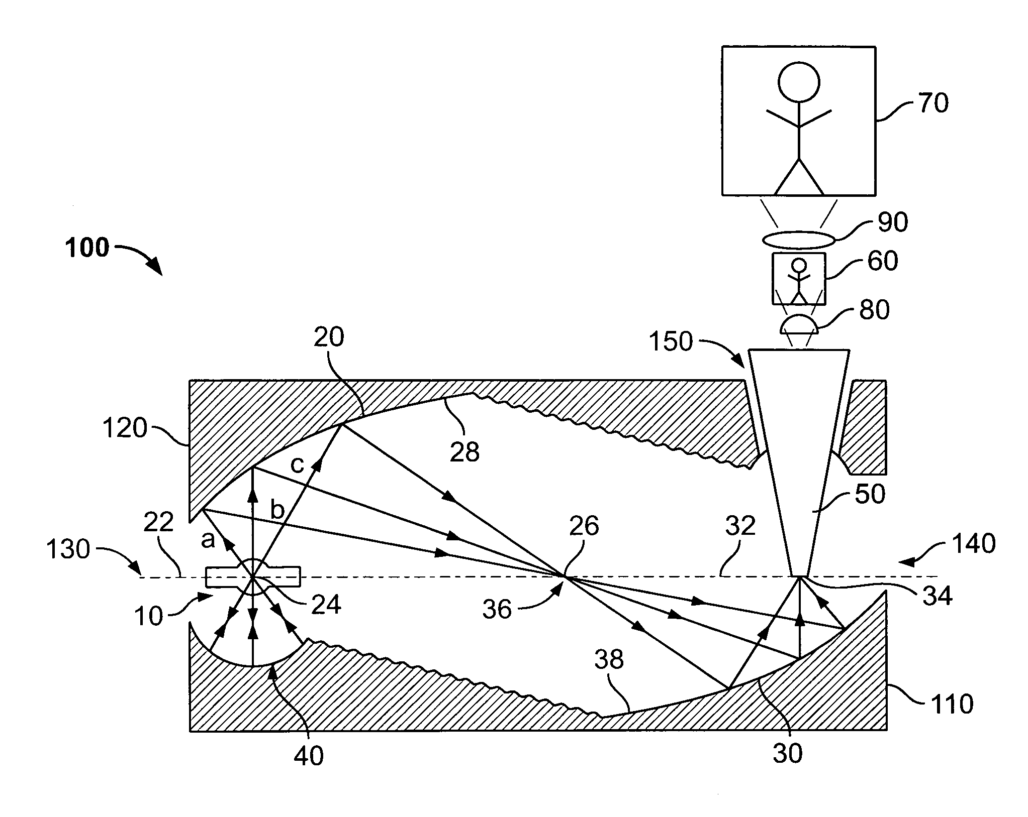
Compact dual ellipsoidal reflector (DER) system having two molded ellipsoidal modules such that a radiation receiving module reflects a portion of rays to an opening in the other module
a dual-axis, ellipsoidal technology, applied in the direction of instruments, lighting and heating apparatus, optical elements, etc., can solve the problems of degrading the overall efficiency of the optical illumination and projection system, degrading the system brightness, and reducing the incidence angle of rays, so as to reduce the loss of fresnel reflection, the effect of maximizing the net output coupling efficiency
- Summary
- Abstract
- Description
- Claims
- Application Information
AI Technical Summary
Benefits of technology
Problems solved by technology
Method used
Image

Examples
examples
[0071]A first pair of exemplary optical systems in accordance with the present invention uses a low wattage lamp, in the order of 100 Watts, as the lights source. In the compact DER system 100 in accordance exemplary embodiment of the present invention, each of the first and second molded ellipsoidal reflector sections has a diameter of 2.5 inches, and the separation between the source and target (i.e., the distance between the foci) is about 5 inches. For a low wattage reflection system, the ellipsoidal reflector sections can have a greater eccentricity in accordance with an exemplary embodiment of the present invention, the first and second molded ellipsoidal reflector sections can be of similar size, each having diameter of approximately 2.5 inches, but the distance is approximately 2 inches between the source and target.
[0072]In higher wattage applications, the optical system is relatively larger to provide desirable collection of the higher electromagnetic energy levels and to ...
PUM
 Abstract
Description
Claims
Application Information