
Switching power supply

a power supply and switching element technology, applied in the field of switching power supplies, can solve the problems of complex circuit configuration, large circuit size, and more serious malfunction of pwm comparator, and achieve the effect of accurate control of switching element turning-on/off, preventing subharmonic oscillation of pulse signals, and simple circuit configuration

Inactive Publication Date: 2009-04-07
FUJI ELECTRIC CO LTD
View PDF4 Cites 13 Cited by
  • Summary
  • Abstract
  • Description
  • Claims
  • Application Information

AI Technical Summary

Benefits of technology

[0022]It is an object of the invention to provide a switching power supply which can prevent subharmonic oscillation of a pulse signal for current-mode control with a simple circuit configuration and a small circuit and also can accurately control the output voltage even if a CR filter is provided between a resistance for detecting current and a current detection terminal of a controller.
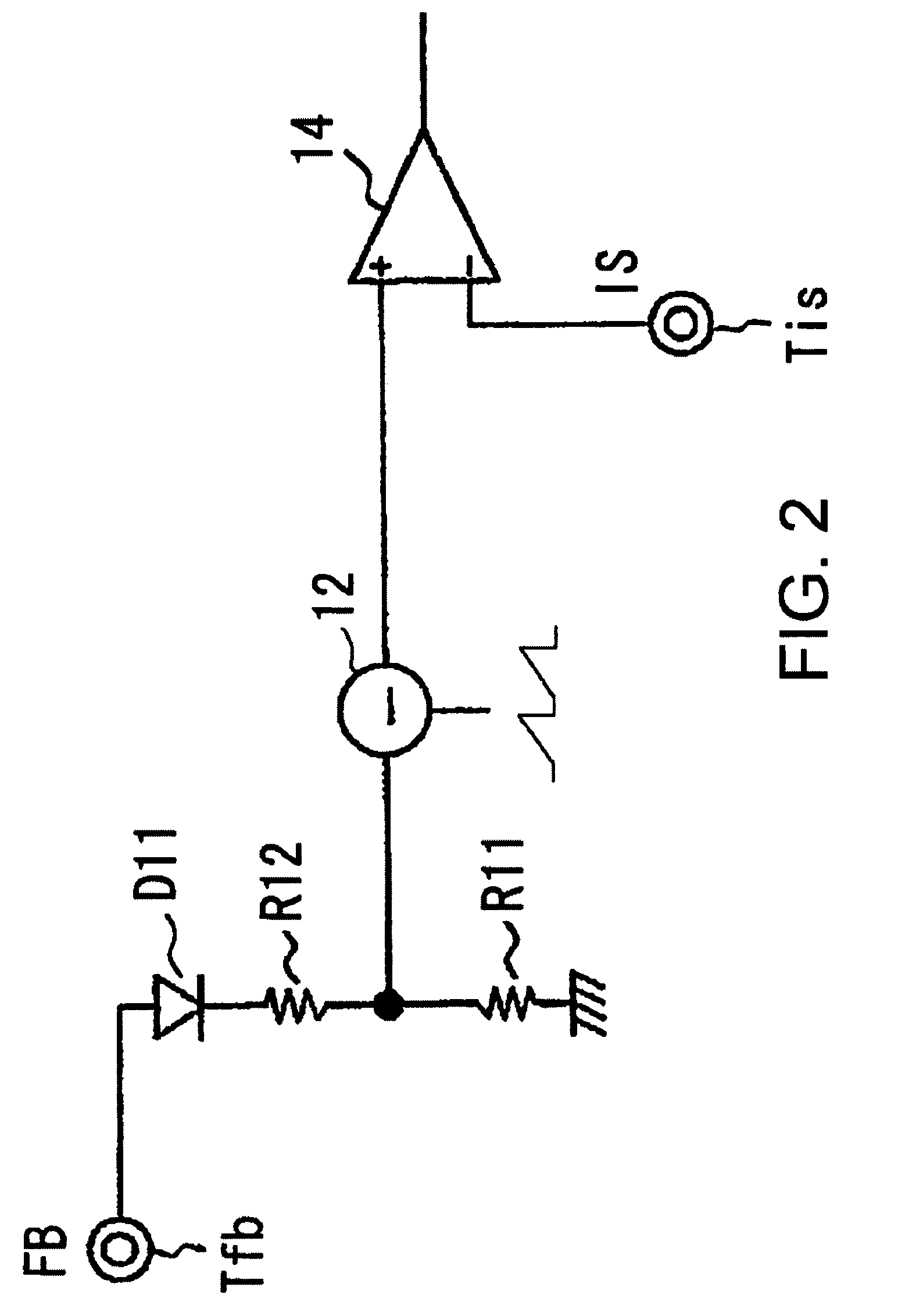
[0024]With the switching power supply described above, since slope compensation is carried out by subtracting a slope compensation signal from an output voltage detection signal, it is possible to accurately control turning-on / off of the switching element and also to prevent subharmonic oscillation of a pulse signal for current-mode control with a simple circuit configuration and a small circuit size.

Problems solved by technology

This may cause a problem, which is described below.
Malfunctioning of the PWM comparator presents a more serious problem if an output from the PWM comparator PWMCMP is stored temporarily in a storage device such as a flip-flop and then turning-on / off of the power transistor PT1 is controlled.
According to claim 4 and Embodiment 3 of Japanese Laid-Open Patent Publication (Kokai) No. 2004-40856 mentioned above, “a signal obtained by superimposing a feedback signal and a slope compensation signal one upon the other” is used, but this configuration presents a problem as described below.
For this reason, the circuit configuration is complicated, and the circuit is large in size.
Specifically, generating a signal that decreases from an initial positive (not zero) value to zero is more difficult than generating a signal that monotonously increases from zero.
Even if a current mirror circuit is used, the source-to-drain junction enters the nonsaturation region when it comes close to zero, and hence the current mirror circuit cannot function properly.
That is, current cannot be constant.

Method used


Image

  • Switching power supply
  • Switching power supply
  • Switching power supply

Examples


Embodiment Construction

[0035]The present invention will now be described in detail with reference to the drawings showing a preferred embodiment thereof.

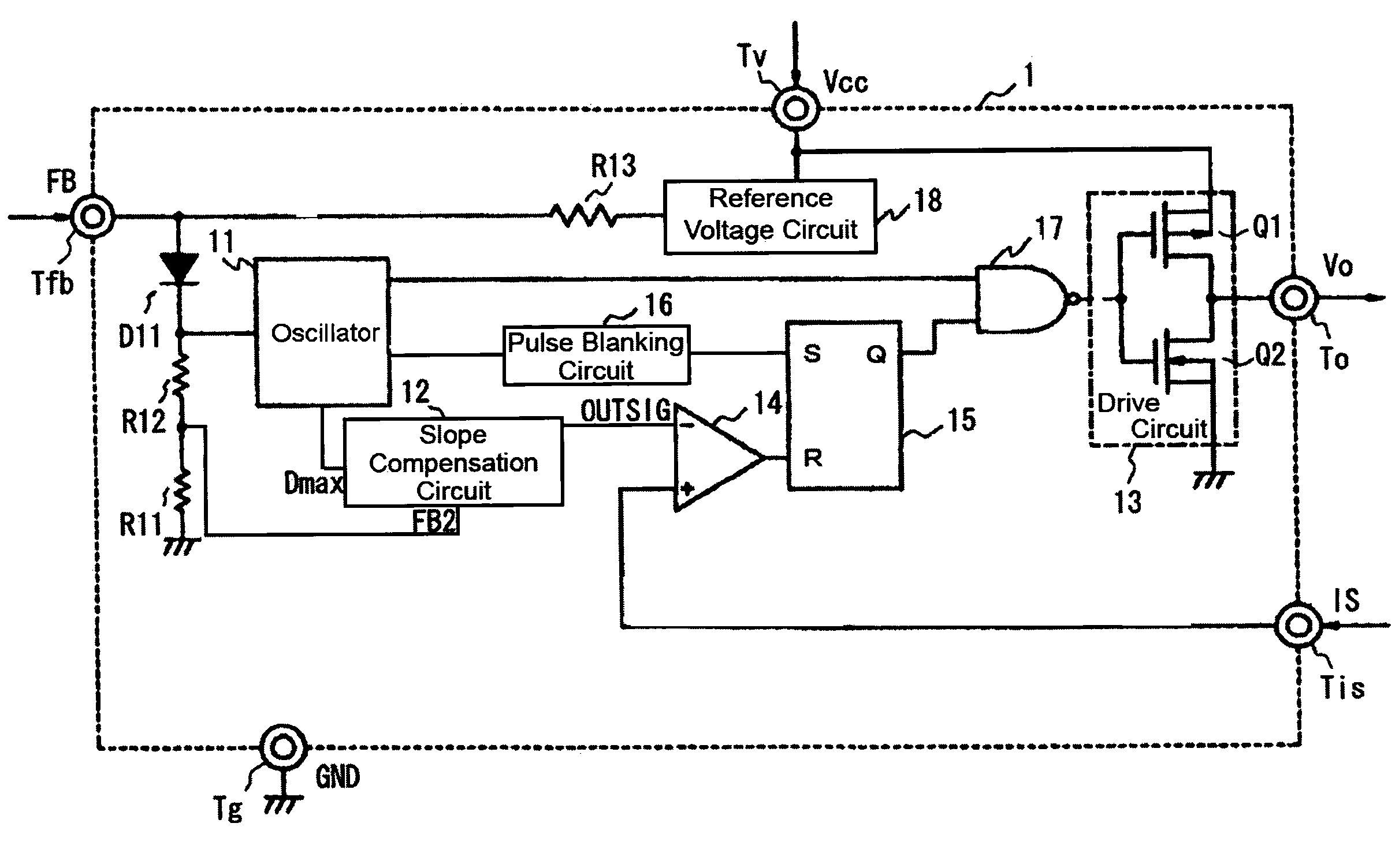
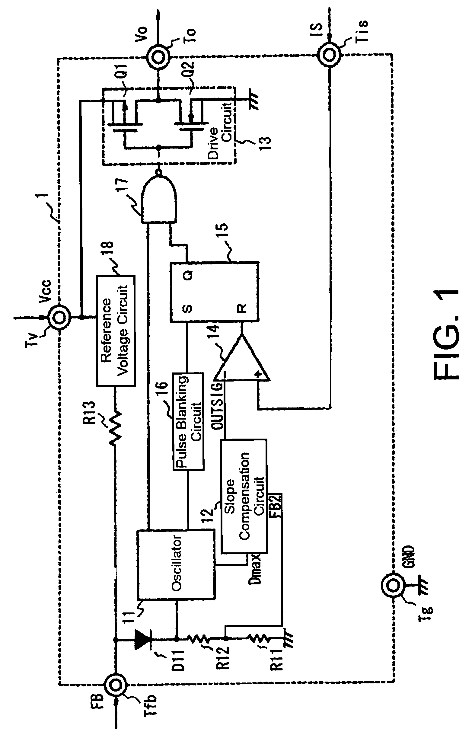
[0036]A switching power supply according to an embodiment of the present invention is identical in overall construction with the construction in FIG. 6. FIG. 1 is a diagram showing an example of the construction of a controller 1 according to the embodiment. The controller 1 is comprised of an oscillator 11 that determines the frequency of a pulse signal for turning on / off a power transistor PT1 (i.e. decreases the frequency at light load) according to a feedback signal FB from a voltage detecting circuit 3, a slope compensation circuit 12 for carrying out slope compensation, described later; a drive circuit 13 comprised of a series circuit consisting of a P-channel MOS transistor Q1 and an N-channel MOS transistor Q2 for driving the power transistor PT1, a PWM comparator that generates a pulse-width modulated pulse signal, a flip-flop 15, a pulse blankin...


PUM


Abstract

A switching power supply, in which a switching element turns on and off electric current flowing on the primary side of an output transformer so as to rectify and output a pulsating flow generated on the secondary side of the output transformer, includes a voltage detecting section that detects an output voltage, a current detecting section that detects electric current flowing through a power transistor as the switching element, a controller that compares a voltage detection signal from the voltage detecting section and a current detection signal from the current detecting section to control the duty of the power transistor during an ON time, and a slope compensation circuit that compensates the rate of change of the voltage detection signal using a slope compensation signal. The slope compensation circuit subtracts the slope compensation signal from the voltage detection signal and outputs the resulting signal to a PWM comparator.

Description

BACKGROUND OF THE INVENTION[0001]1. Field of the Invention[0002]The invention relates to a switching power supply that carries out current-mode control. In particular, the invention relates to a switching power supply that suppresses subharmonic oscillation of a pulse signal for current-mode control.[0003]2. Description of the Related Art[0004]In a switching power supply in which a switching element turns on and off, an electric current flows on the primary side of an output transformer so that a pulsating flow generated on the secondary side of the output transformer is rectified and output. In such a power supply, there may be a case where subharmonic oscillation of a pulse signal for current-mode control, which drives the switching element by PWM (pulse-width modulation), occurs during current-mode control. To cope with this, there has been proposed a switching power supply that suppresses such subharmonic oscillation (see e.g. Japanese Laid-Open Patent Publication (Kokai) No. 20...

Claims


Application Information

Patent Timeline
Patent Type & Authority Patents(United States)
IPC IPC(8): H02M3/335H02M3/24
CPCH02M3/33523H02M2001/0029H02M1/0029
Inventor KASHIMA, MASATO
Owner FUJI ELECTRIC CO LTD
Learn More