
Signal transmitting method in mobile communication system

a mobile communication system and signal transmitting technology, applied in multiplex communication, diversity/multi-antenna systems, multi-modulation transmitter/receiver arrangements, etc., can solve problems such as insufficient detection of symbols, and achieve the effect of improving the capability of symbol detection

Inactive Publication Date: 2009-04-07
LG ELECTRONICS INC
View PDF17 Cites 19 Cited by
  • Summary
  • Abstract
  • Description
  • Claims
  • Application Information

AI Technical Summary

Benefits of technology

The present invention provides a method and apparatus for transmitting signals in a mobile communication system using multiple antennas. The method involves allocating bit-mapped symbols to the multiple antennas based on their correlation among each other and the detection efficiency of each symbol. This allocation helps improve symbol detection and reduces interference between the signals transmitted through the multiple antennas. The technical effects of the invention include improved signal transmission and better symbol detection.

Problems solved by technology

However, the independency of the channels is not always maintained resulting in the symbols being not detected properly.

Method used


Image

  • Signal transmitting method in mobile communication system
  • Signal transmitting method in mobile communication system
  • Signal transmitting method in mobile communication system

Examples


Embodiment Construction

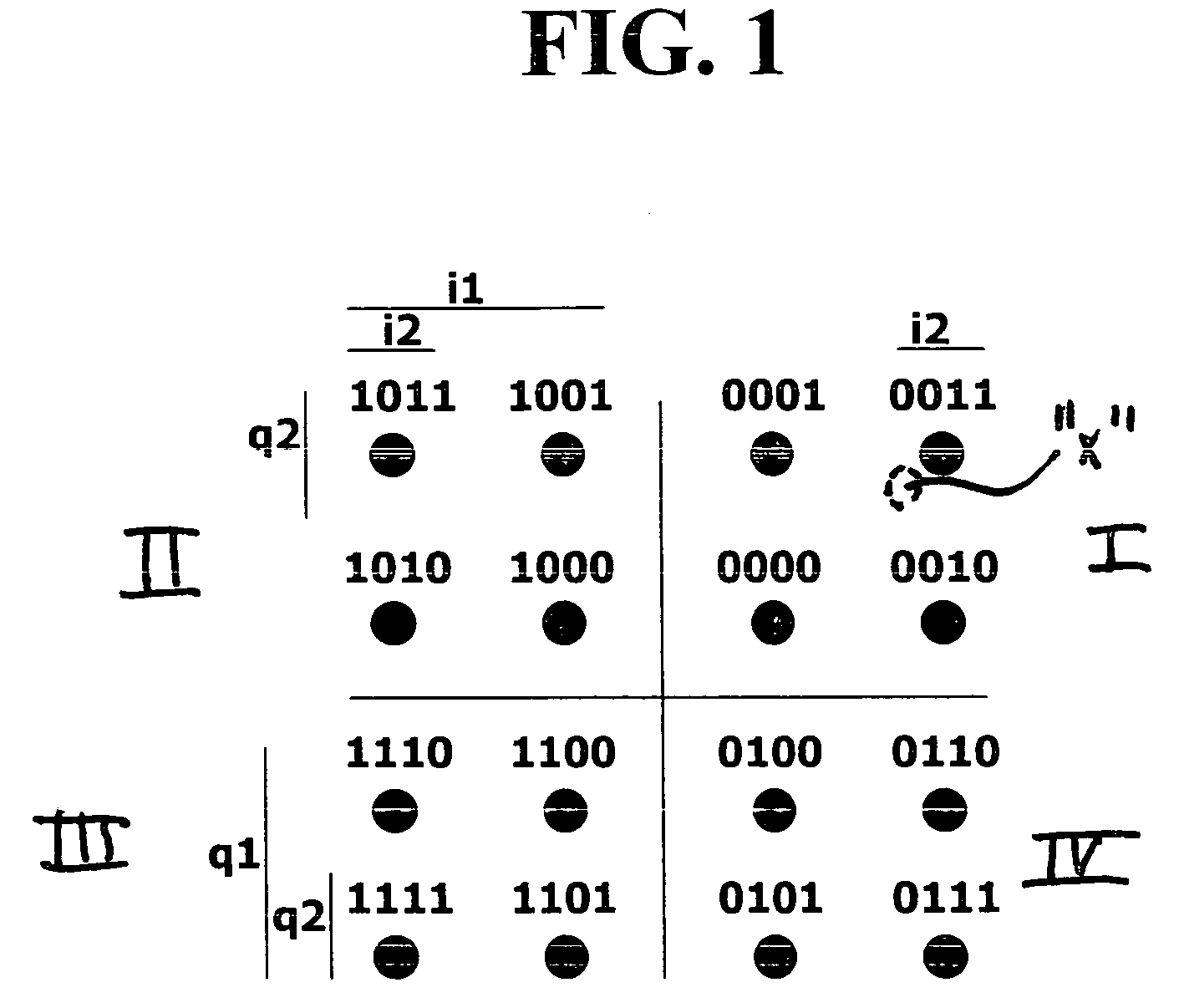
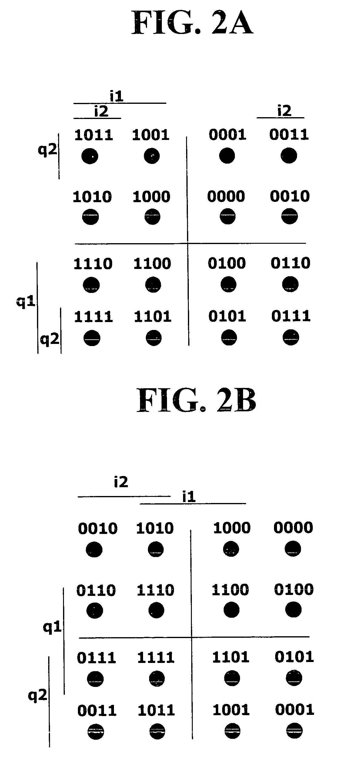
[0021]Assuming the order of four bits in 16 QAM is i1, q1, i2 and q2, the detection reliability of a bit differs depending on which value is allocated to each bit. Namely, in terms of positions, i1 and q1 have a higher reliability than i2 and q2 regardless of a bit value, and i2 and q2 have a relatively low reliability compared to i1 and q1. For example, with reference to the 16 QAM constellation in FIG. 1, the bit reliability of i1, q1 is greater than the bit reliability of i2, q2. That is, the first two bits are the same in each quadrant I, II, III and IV, and thus it is more likely that the first two bits of a mapped symbol into one of the quadrants are correct. For example, assume a data point “x” is detected in the first quadrant as shown in FIG. 1, and you are trying to determine the bit value of the detected data point (i.e., is the bit value 0011, 0001, 0000 or 0010?). Note that the first two bits are 00 for each data point in quadrant I. The same is not true for the bit val...


PUM


Abstract

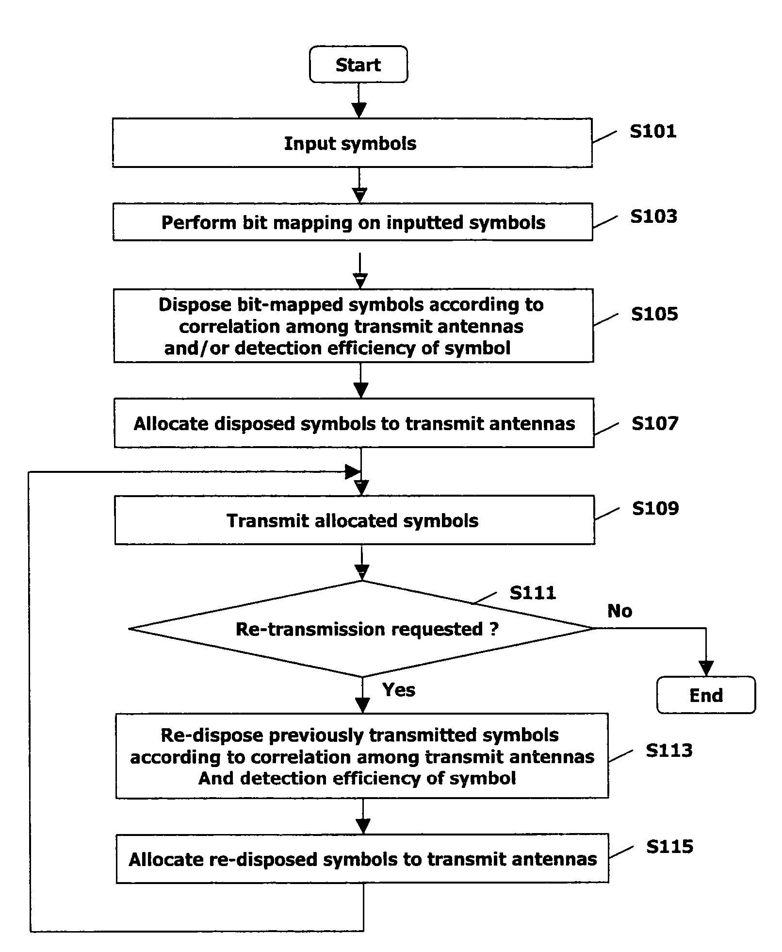
A method of transmitting a signal in a mobile communication system using multiple antennas including allocating bit-mapped symbols to the multiple antennas based on a correlation among the multiple antennas. Further, allocating the bit-mapped symbols allocates bit-mapped symbols transmitted from antennas having a higher correlation among each other to be retransmitted from antennas having a lower correlation among each other, and allocates bit-mapped symbols transmitted from antennas having a lower correlation among each other to be retransmitted from antennas having a higher correlation among each other. In another example, allocating the bit-mapped symbols allocates the bit-mapped symbols to multiple antennas according to a detection efficiency of each symbol in addition to the correlation among the multiple antennas.

Description

BACKGROUND OF THE INVENTION[0001]1. Field of the Invention[0002]The present invention relates to a signal transmitting method and apparatus in a mobile communication system using multiple antennas.[0003]2. Description of the Background Art[0004]In most coded modulation systems used in a wireless environment, gray mapping is performed on data (symbols) of 8 PSK (Phase Shift Keying) or 16 QAM (Quadrature Amplitude Modulation). For example, FIG. 1 illustrates a constellation using gray mapping for 16 QAM.[0005]As shown in FIG. 1, when gray mapping is used, four bits are required to form one symbol of 16 QAM. In a HSDPA (High Speed Downlink Packet Access) system using a HARQ (Hybrid Automatic Repeat Request) function the data is transmitted via an antenna and is received by a receiver. If a retransmission is required, the order of bits of data that has been first transmitted is changed and then the data is retransmitted. Such an operation is called a constellation rearrangement.[0006]Th...

Claims


Application Information

Patent Timeline
Patent Type & Authority Patents(United States)
IPC IPC(8): H04L27/00H04B7/02H04J99/00H04L1/00H04L1/02H04L1/06H04L1/18
CPCH04B7/0671H04L1/0003H04L1/06H04L1/1812H04L1/1893H04L5/0023H04L5/0044H04L27/0008H04L27/3416H04B7/02
Inventor SHIM, DONG-HEEKIM, BONG-HOE
Owner LG ELECTRONICS INC
Learn More