Apparatus and method for controlling the pressure in an ink reservoir of an ink jet printer

a technology of ink jet printer and ink reservoir, which is applied in the direction of printing, other printing apparatus, etc., can solve the problems of common inability, and achieve the effect of simple and durabl

Active Publication Date: 2009-04-14
OCE TECH
View PDF19 Cites 17 Cited by
  • Summary
  • Abstract
  • Description
  • Claims
  • Application Information

AI Technical Summary

Benefits of technology

[0004]Accordingly, it is an object of the present invention to provide a relatively simple and durable device for controlling the pressure in an ink reservoir of an inkjet printer.
[0007]In a preferred embodiment the pressure applying means includes at least one buffer reservoir. The buffer reservoir is adapted to enclose a (gaseous) medium with a certain (under)pressure which communicates with the gaseous volume within the ink reservoir. In this manner it is also possible to achieve a desired underpressure and / or overpressure in the ink reservoir without making use of a conventional pump. The volume of the buffer reservoir can be either constant, preferably of between 1 and 20 liter, or can be adjustable. In the latter embodiment the capacity of the buffer reservoir can be adjusted, for example by means of a plunger. In a particular preferred embodiment the buffer reservoir is positioned between the ink reservoir and the pump. In this case, the buffer reservoir can be applied to absorb pumping pulses generated by the pump to avoid (extreme) fluctuations of the internal pressure within the ink reservoir. Moreover, the buffer reservoir can act as a surrogate pump in case the actual pump is turned off for example due to a power breakdown, or in case the actual pump is temporary switched to a standby mode, for example between two print sessions. Preferably, the buffer reservoir is isolatable from the communication between the pump and the ink reservoir, for example in case where a temporary overpressure needs to be applied to the ink reservoir for rinsing the ink reservoir. Isolation of the buffer reservoir from the pump and the ink reservoir can be realized by means of a switch, in particular a pneumatic or even a hydraulic or electronic switch. In an alternative embodiment it is conceivable to apply multiple buffer reservoirs, wherein, for example, each printhead may be in communication with a separate buffer reservoir. In this manner, the pressure per printhead can be regulated more precisely and even independent of the pressures prevailing in the other printheads.
[0008]While the printhead of an ink jet printer is generally mounted on a moving carriage, the pressure control apparatus is preferably mounted on a stationary frame of the printer and is preferably connected to the ink reservoir on the printhead through a flexible hose. Application of a flexible hose commonly increases the degree of freedom of design of the inkjet printer, whereas the deformation of the hose will easily be adapted to the mutual orientation of the printhead(s) on one side and the apparatus according to the present invention on the other side. If the printhead contains a plurality of ink reservoirs, for example in a color printer, all ink reservoirs may, not necessarily be connected to the same pressure control apparatus.

Problems solved by technology

Both pressures (underpressure and overpressure) can be detected by the electronic pressure sensor, which is commonly not possible by means of the conventional mechanical (one-way) detecting means, the latter commonly being able to detect merely an underpressure.
However, as mentioned above, the underpressure in the ink reservoir during operational use is rather critical and is normally placed between 5 and 50 millibar with an allowed deviation of certain millibars dependent on the desired underpressure in the ink reservoir.

Method used


Image

  • Apparatus and method for controlling the pressure in an ink reservoir of an ink jet printer
  • Apparatus and method for controlling the pressure in an ink reservoir of an ink jet printer
  • Apparatus and method for controlling the pressure in an ink reservoir of an ink jet printer

Examples


Embodiment Construction

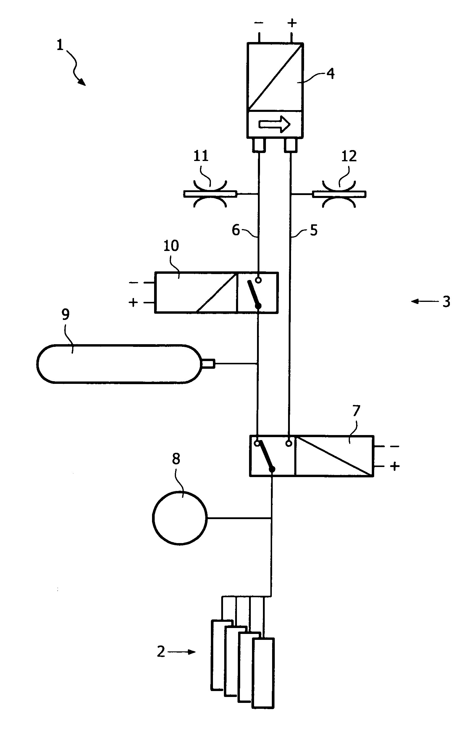
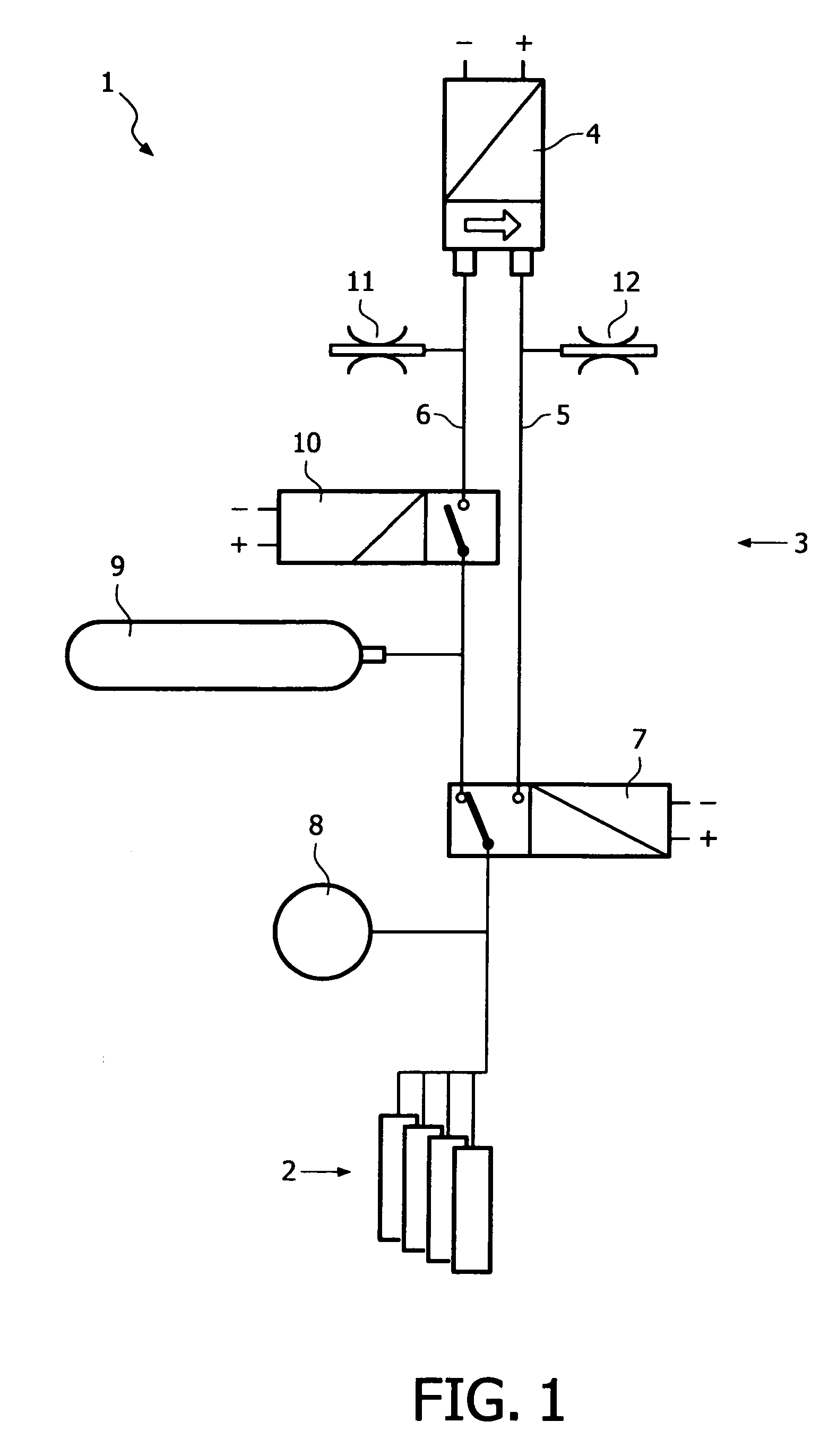
[0014]FIG. 1 shows a schematic view of a preferred embodiment of an assembly 1 of multiple printheads 2 and an apparatus 3 for controlling the pressure in the printheads according to the present invention. The apparatus 3 includes a membrane pump 4, the capacity of which can be adjusted by applying variable frequencies to the pump 4. The pump 4 is adapted to generate an overpressure and / or an underpressure and is in communication with ink reservoirs incorporated in the printheads 2. Both an overpressure conduit 5 and an underpressure conduit 6 are coupled to a diverter valve 7, the latter being adapted to apply either an overpressure or an underpressure in the ink reservoirs of the printheads. Under normal printing conditions a critical underpressure in the ink reservoirs is required of about between 5 and 20 millibar, wherein the diverter valve 7 is switched such, that the ink reservoirs are in communication with the underpressure conduit 6, and wherein the overpressure conduit 5 i...


PUM


Abstract

An apparatus for controlling the pressure in an ink reservoir of an ink jet printer which includes at least one ink reservoir of an ink jet printer, a pressure applying device for applying a pressure in the ink reservoir, the pressure applying device communicating with the ink reservoir via a first conduit, a buffer reservoir communicating a gasteous medium with the ink reservoir via a second conduit different from the first conduit, a detection system for monitoring the actual pressure in the ink reservoir, the detection system including at least one electronic pressure sensor, and a controller for controlling the pressure applying means dependent on the actual pressure monitored by the detection system.

Description

BACKGROUND OF THE INVENTION[0001]The present invention relates to an apparatus for controlling pressure in an ink reservoir of an ink jet printer. The present invention also relates to an ink jet printer including a printhead with an ink reservoir containing liquid ink and a gas volume above the level of the ink. The present invention further relates to a method for controlling pressure in an ink reservoir of an ink jet printer.[0002]An ink jet printer typically contains printheads having one or more nozzle arrays and an ink reservoir from which liquid ink is supplied to the nozzles of the nozzle arrays, so that ink droplets may be ejected from the nozzles by thermal or piezoelectric action, as is generally known in the art. When the level of ink in the ink reservoir is higher than the level of the nozzles, the ink reservoir should be maintained at subatmospheric pressure in order to avoid ink from leaking out through the nozzles. Since the difference between the internal pressure i...

Claims


Application Information

Patent Timeline
Patent Type & Authority Patents(United States)
IPC IPC(8): B41J29/38B41J2/175
CPCB41J2/17556
Inventor NOTTELMAN, FRANK J. H.HENNISSEN, JEROEN J. M.
Owner OCE TECH
Why Eureka
Try Eureka