Forward facing rowing attachment with rolling seat

a technology of forward facing rowing and rolling seat, which is applied in the field of watercraft, can solve the problem of inconvenient facing the stern

Inactive Publication Date: 2009-04-14
NESSETH MICHAEL J
View PDF10 Cites 6 Cited by
  • Summary
  • Abstract
  • Description
  • Claims
  • Application Information

AI Technical Summary

Problems solved by technology

Facing the stern is inconvenient, since the rower must look over his or her shoulder to see where the craft is heading and what obstructions are present.

Method used


Image

  • Forward facing rowing attachment with rolling seat
  • Forward facing rowing attachment with rolling seat
  • Forward facing rowing attachment with rolling seat

Examples


Embodiment Construction

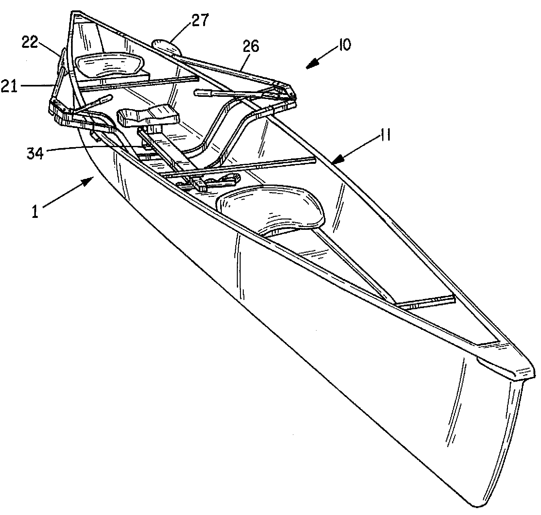
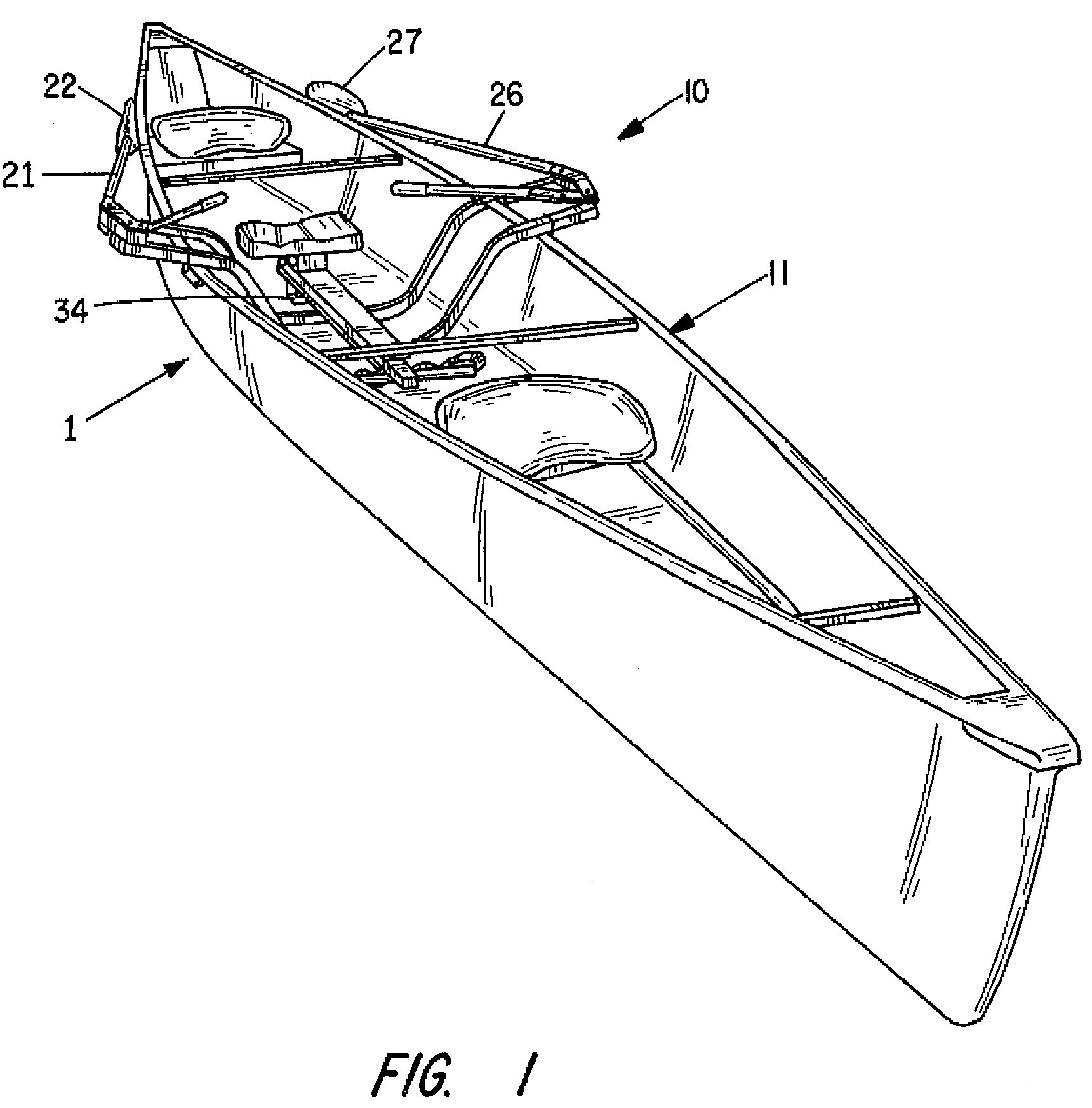
[0019]FIGS. 1 and 2 show the present invention as a frame assembly 10 that is particularly useful as a component of a forward-facing rowing accessory 1 that can be retrofitted into an existing canoe 11 as shown, or into other small watercraft typically propelled by a human.

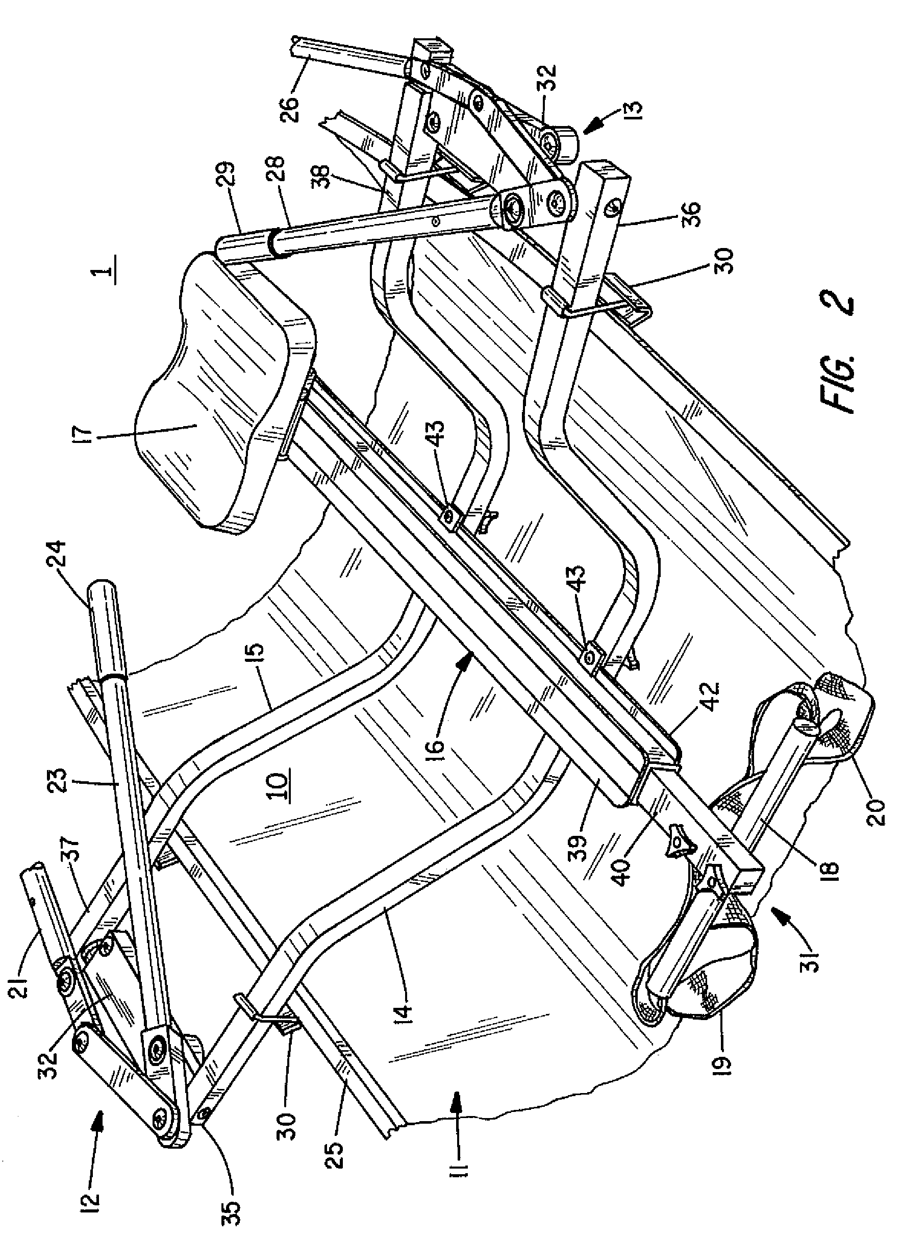
[0020]The frame assembly 10 of the present invention includes first and second frame members 14 and 15, a track assembly 16, a seat assembly 17 that smoothly slides on track assembly 16, and a telescoping footrest 31. FIGS. 1-3 show these components (absent seat assembly 17 in FIG. 3) in assembled form for use in a canoe 11.

[0021]FIG. 3 shows the accessory 1 with the seat assembly 17 detached from track assembly 16 and the individual oar mechanisms 12 and 13 attached to the frame members 14 and 15. FIG. 4 shows separate frames members 14 and 15 attached to the oar assemblies 12, and with seat assembly 17 and track assembly 16 detached from the frame members 14 and 15.

[0022]The design of frame assembly 10 provides ...


PUM


Abstract

A frame assembly forming a portion of a rowing accessory is to be mounted within a watercraft, to which frame assembly is attached a seat and oars. The frame assembly comprises first and second frame members each having the general shape of a winged U. First and second wing portions of each frame member extend outwardly from upper ends of the frame members. A track assembly has a beam attached to lower portions of the frame members at spaced apart connection points along the length of the beam. A seat assembly attaches to and slides along the beam. First and second hinge plates each have a first end attached at an outboard end of one wing portion of the first frame member, and a second end attached at an outboard end of one wing portion of the second frame member.

Description

[0001]This is a regular application filed under 35 U.S.C. §111(a) claiming priority under 35 U.S.C. §119(e)(1), of provisional application Ser. No. 60 / 933,197, filed Jun. 5, 2007, and incorporated herein by reference in its entirety.BACKGROUND OF THE INVENTION[0002]The present invention relates generally to watercraft and particularly, to canoes, rowboats, and other small water vessel. As is well known, canoes are traditionally propelled with paddles. Canoeists both propel and steer the canoe with the paddles. Since the paddling motion is to the side of the canoeist and only the arm muscles are involved, speed depends on good arm strength and an easily driven canoe. Canoeists face the bow of the canoe.[0003]Small rowboats are typically propelled by pairs of oars that pivot in oarlocks fastened to the gunwales (upper edges) of the rowboat hulls. The oarlocks each have a vertical axis pivot that allows a rower to apply force to the oars in a substantially horizontal plane with the oar...

Claims


Application Information

Patent Timeline
Patent Type & Authority Patents(United States)
IPC IPC(8): B63H16/067
CPCB63H16/105
Inventor NESSETH, MICHAEL J.
Owner NESSETH MICHAEL J
Why Eureka
Try Eureka