Speed control system and method for watercraft

a technology of speed control system and watercraft, which is applied in the direction of electrical control, marine propulsion, vessel construction, etc., can solve the problems of undesirable delay, burden on the operator, and inconvenient conventional speed control system

Inactive Publication Date: 2005-04-26
MITSUBISHI ELECTRIC CORP +1
View PDF10 Cites 66 Cited by
  • Summary
  • Abstract
  • Description
  • Claims
  • Application Information

AI Technical Summary

Benefits of technology

[0010]One embodiment of the present invention provides a speed control system and method for a watercraft that does not require the operator to operate a mode selector in switching to the manual control mode from the constant speed mode. The control system in the embodiment releases the constant speed mode whenever the operator operates an operating device such as, for example, a remote controller and allows the operator to control the speed of the watercraft in the manual control mode.
[0017]In accordance with a further aspect of the present invention, a speed control system for a watercraft comprises a speed control system that automatically controls a speed of the watercraft according to a pre-specified target speed setting when the watercraft is in a regulated speed mode. A mode control switch is operable by an operator to switch the watercraft into and out of the regulated speed mode. A speed of the watercraft is controlled according to a position of a throttle lever when the watercraft is not in the regulated speed mode. A controller is responsive to operator movement of the throttle lever with the watercraft in the regulated speed mode by taking the watercraft out of the regulated speed mode to allow the operator to control the watercraft's speed manually, whereby the operator can take the watercraft out of the regulated speed mode by movement of the throttle lever without operating the mode control switch.

Problems solved by technology

On the other hand, however, the conventional speed control system is sometimes inconvenient.
This operation is not only burdensome for the operator but also takes time, causing an undesirable delay before deceleration occurs.
This delay may also be problematic in other scenarios in which the operator needs to desires to rapidly adjust the boat's speed.

Method used


Image

  • Speed control system and method for watercraft
  • Speed control system and method for watercraft
  • Speed control system and method for watercraft

Examples


Embodiment Construction

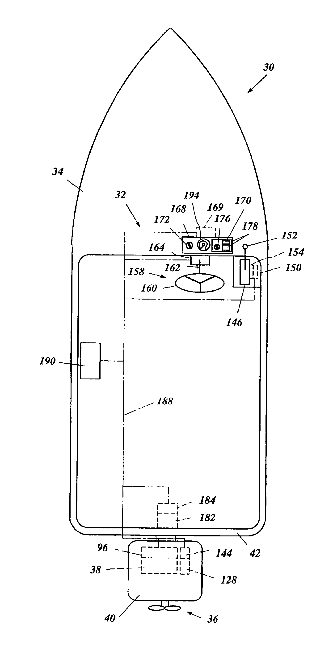
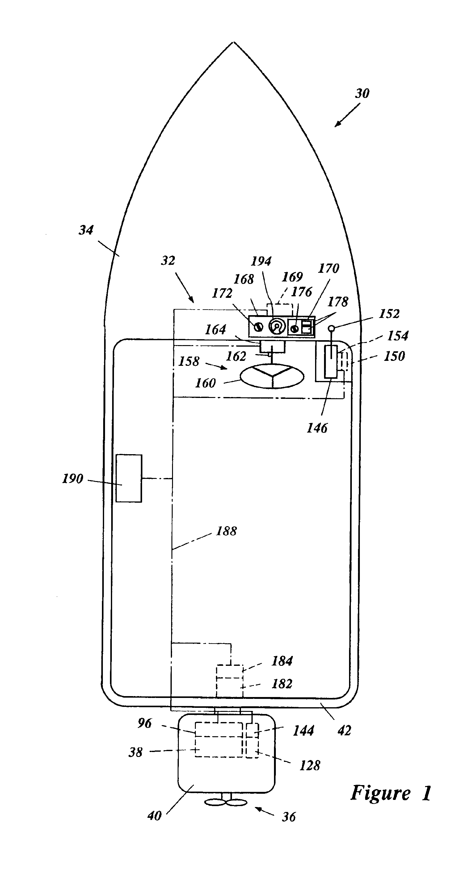
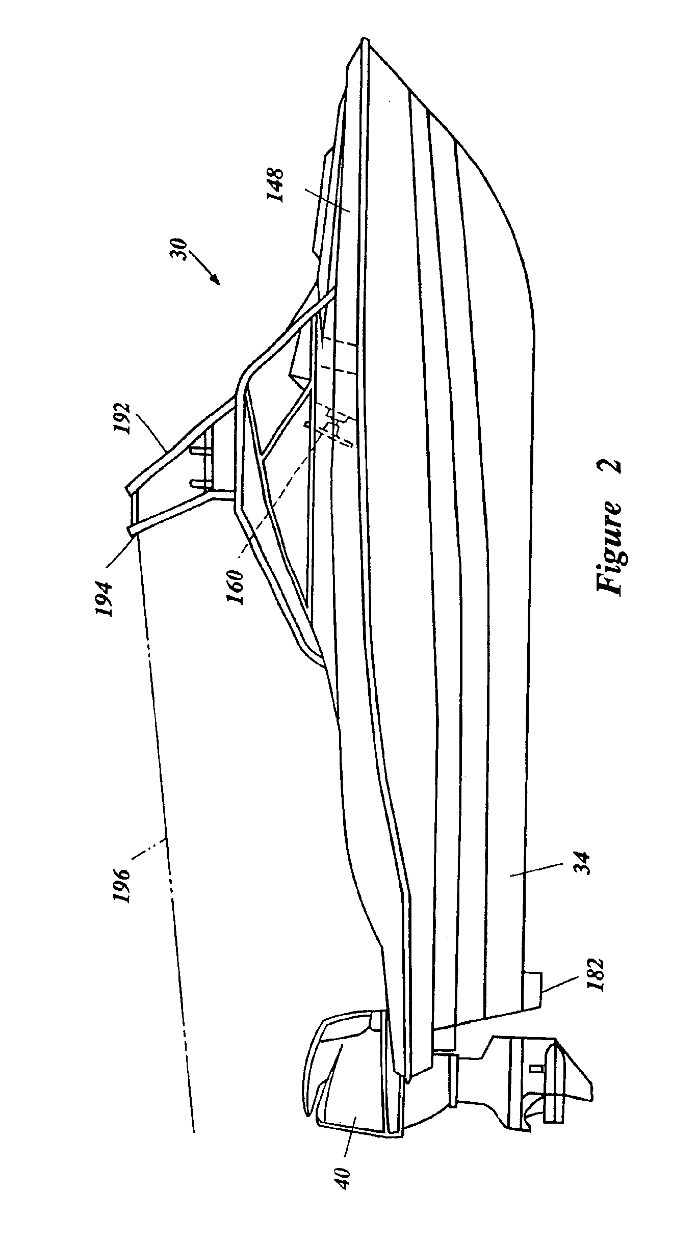
[0032]With reference to FIGS. 1-7, a watercraft 30 configured in accordance with certain features, aspects and advantages of the present invention is described below. Although the watercraft 30 includes a communication network 32 in the illustrated embodiment, those skilled in the art will appreciate that the invention may be practiced without the use of a network. In addition, although the decision logic in the preferred embodiment is distributed across multiple nodes, a centralized (non-distributed) computing architecture may alternatively be used in which most of the functionality of the nodes is implemented within a program executed by a single computer processor.

[0033]With reference to FIG. 1, the watercraft 30 has a hull 34. The watercraft 30 also has a propulsion device 36 that propels the hull 34 and an internal combustion engine 38 that powers the propulsion device 36. In the illustrated embodiment, an outboard motor 40 mounted on a transom 42 of the hull 34 incorporates th...


PUM


Abstract

A watercraft has an engine and a remote controller. The engine has a throttle valve unit. The remote controller provides a command signal indicative of a position of the throttle valve unit. A watercraft velocity sensor senses an actual speed of the watercraft to provide an actual speed signal. A control data input device selectively provides a control device with a manual mode signal and a constant speed mode signal. The constant speed mode signal is accompanied by a target speed signal. The control device controls the throttle valve unit based upon the command signal in the manual mode. The control device controls the throttle valve unit in the constant speed mode such that an actual speed of the watercraft coincides with the target speed of the watercraft once a state of equilibrium is reached. The control device starts the manual mode in place of the constant speed mode without the manual mode signal if the command signal changes while the control device controls the throttle valve unit in the constant speed mode.

Description

PRIORITY INFORMATION[0001]The present application is based on and claims priority under 35 U.S.C. § 119 to Japanese Patent Application No. 2002-307950, filed on Oct. 23, 2002, the entire content of which is expressly incorporated by reference herein.BACKGROUND OF THE INVENTION[0002]1. Field of the Invention[0003]The present invention generally relates to a speed control system and method for a watercraft, and more particularly relates to an improved speed control system and method that controls a speed of a watercraft selectively using at least two control modes.[0004]2. Description of Related Art[0005]Computerized controls have become popular in recent years for watercrafts. In one arrangement, a watercraft has a propulsion device that propels the watercraft. Typically, an outboard motor can have such a propulsion device that is powered by an engine. An air intake device for the engine can incorporate a throttle valve unit that has a throttle valve to regulate an amount of air or r...

Claims


Application Information

Patent Timeline
Patent Type & Authority Patents(United States)
IPC IPC(8): B63H21/00B63H21/22B63H21/21F02D29/02F02D41/14F02D9/02F02D11/10F02D31/00
CPCB63H21/21B63H21/22F02D31/006F02D29/02F02D11/105
Inventor OKUYAMA, TAKASHISUGIMOTO, TAKASHIITOI, MAKOTO
Owner MITSUBISHI ELECTRIC CORP
Why Eureka
Try Eureka