Regenerative motor propulsion systems

a technology of regenerative motors and propulsion systems, applied in the direction of propulsion-based emission reduction, gas pressure propulsion mounting, navigational aid arrangements, etc., can solve the problems of less developed watercraft regenerative technology, improve fuel economy, optimize the effect of regeneration efficiency

Inactive Publication Date: 2009-01-27
TECHNIPOWER SYST INC
View PDF21 Cites 67 Cited by
  • Summary
  • Abstract
  • Description
  • Claims
  • Application Information

AI Technical Summary

Benefits of technology

[0006]An object of an embodiment is to provide improved fuel economy. Another object according to an embodiment is to provide improved use of equipment such as motors, sails, propellers, transmissions and batteries. Yet another object is to harvest energy from a naturally occurring source such as wind, waves, potential energy of a vehicle at a higher elevation traveling to a lower elevation, and kinetic energy obtained from a braking vehicle. Yet another object is to obtain improved overall transportation efficiency of watercraft with a system that integrates information about boat speed and one or more other parameters such as wind speed, sail use, and wave action, to adjust motor power.
[0007]These and other objects can be met by embodiments as described here in. One embodiment provides a vehicle or watercraft regeneration system, comprising at least one electric motor on a vehicle or watercraft capable of generating electricity; and a controller for the at least one motor; wherein the controller comprises circuitry for biasing the electric motor during regeneration to optimize the efficiency of the regeneration. Another embodiment provides a regeneration system that further comprises an electricity storage device such as a battery, a capacitor, an electrolysis unit that generates hydrogen from water, and a flywheel. Yet another embodiment provides an efficiency enhancing system for a watercraft or vehicle, comprising at least one electric motor capable of generating electricity; a controller for the at least one motor; and an electrical connection between the at least one motor and the controller, where in the controller adjust one or more magnetic fields of the electric motor during regeneration to optimize the efficiency of the regeneration. Yet another embodiment provides a method for increasing efficiency of regeneration of a watercraft of vehicle powered by at least one electric motor, comprising, sensing when a regeneration event will occur; activating one or more electric motors to place the one or more motors in a more efficient state of regeneration; and regenerating electricity.
[0008]Yet another embodiment provided a method of increasing regeneration efficiency of a sail boat that comprises a motor / generator, comprising: monitoring at least wave activity, wind activity, boat attitude, boat speed, and motor speed to generate one or more signals, determining a down wave condition suitable for a regeneration event from the one or more signals, and biasing the motor / generator before or during the down wave condition for enhanced regeneration performance. Still another embodiment is a sail boat regeneration system comprising: a motor—generator coupled to a propeller, a controller electrically connected to the motor—generator, the controller comprising circuitry for biasing the motor / generator, to improve regeneration efficiency. Yet another embodiment is a method of increasing regeneration efficiency of a sail boat that comprising, a motor / generator, comprising, monitoring at least one wave activity, wind activity, boat speed, boat attitude, and motor speed to generate one or more signals, determining a down wave condition suitable for a regeneration event from the one or more signals, and biasing the motor—generator before or during the down wave condition for enhanced regeneration performance.

Problems solved by technology

Another problem is that, while regeneration for land vehicles such as golf carts, cars and buses has been well implemented, regeneration for watercraft is in contrast much less developed.

Method used


Image

  • Regenerative motor propulsion systems
  • Regenerative motor propulsion systems
  • Regenerative motor propulsion systems

Examples


Embodiment Construction

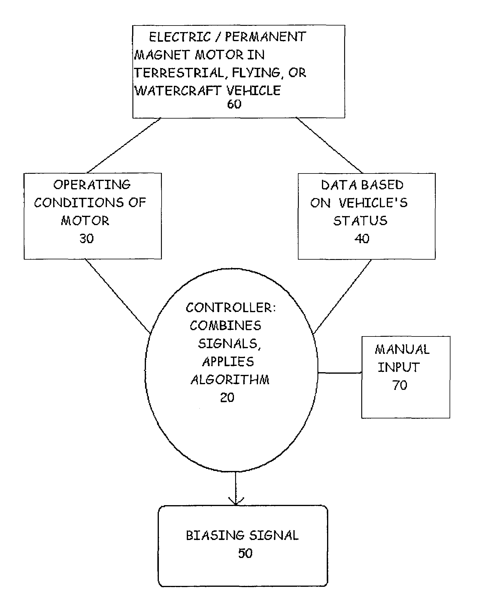
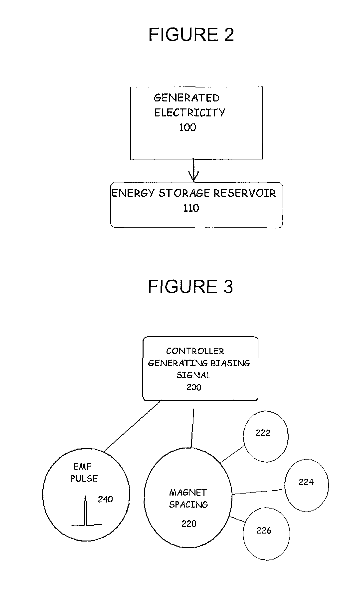
[0016]Methods, systems, materials and algorithms were discovered that enhance regeneration efficiency. In one embodiment a bias is applied to an electric generator (or dual use motor / generator) to alleviate internal friction forces and provide improved regeneration. In a desirable embodiment this occurs at a low rotational shaft speed below the designed optimum speed of the generator. In another embodiment where a motor / generator alternately powers and regenerates a vehicle such as a watercraft, the powering motor rpm is adjusted prior to switching over to regeneration, for improved overall performance.

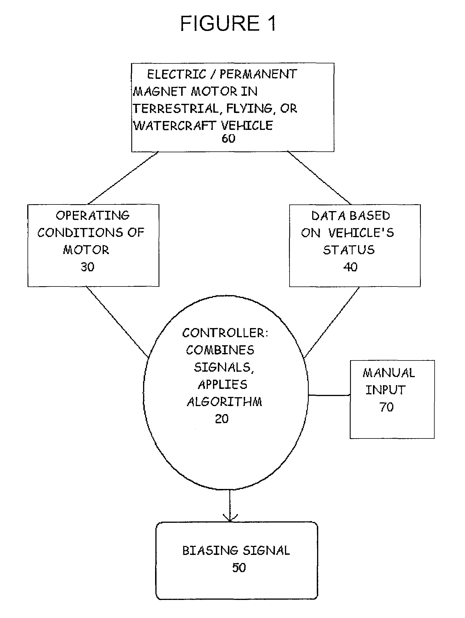
[0017]A wide variety of vehicles and conditions of their use are contemplated for embodiments. For example, a propeller driven airplane may convert kinetic energy of propeller movement, when descending altitude, into electrical energy for heating a carburetor, heating wing surfaces or for charging a battery or other storage device. An automobile, truck, fork lift, or golf cart, upon d...


PUM


Abstract

A vehicle or watercraft regeneration system includes at least one electric motor capable of generating electricity and a controller for the at least one motor; wherein the controller to optimize the efficiency of the regeneration. The controller can optimize efficiency by including comprises circuitry for biasing the electric motor during regeneration. Also provided is a regeneration system that further comprises an electricity storage device such as a battery, a capacitor, an electrolysis unit that generates hydrogen from water, and a flywheel. In addition, an efficiency enhancing system for a watercraft or vehicle includes at least one electric motor capable of generating electricity; a controller for the at least one motor; and an electrical connection between the at least one motor and the controller, where in the controller adjust one or more magnetic fields of the electric motor during regeneration to optimize the efficiency of the regeneration. Methods for increasing efficiency of regeneration of a watercraft of vehicle powered by at least one electric motor are also disclosed.

Description

RELATED APPLICATIONS[0001]This application claims priority to U.S. Provisional Application Ser. No. 60 / 539,978, filed on Jan. 30, 2004 and entitled “Regenerative Motor Propulsion Systems,” which provisional application is incorporated herein by reference.FIELD OF THE INVENTION[0002]The invention relates generally to electric motor and generator control and more specifically to electrical power regeneration in vehicles such as automobiles and watercraft.BACKGROUND[0003]Energy efficiency has become an important factor in electric transportation machines. A particularly good technique for improving overall efficiency in this field is regeneration. Regeneration may involve converting kinetic energy of a vehicle (such as a car, truck, bus or watercraft) into stored electrical energy. In many instances, an electric motor converts electrical energy into kinetic motion, and the same motor, when operated as a regenerator, converts kinetic energy back into electrical energy. The electric ener...

Claims


Application Information

Patent Timeline
Patent Type & Authority Patents(United States)
IPC IPC(8): H02P3/14B60K6/48B60W10/08B63B49/00B63H21/20G05F1/67H02K21/00
CPCB60L7/10B63H21/20B60K6/48B63H9/00B63H21/17Y02T90/46B63J2003/046Y02T10/6221Y02T70/5209Y02T70/5236Y02T70/70B63H2021/202Y02T10/62Y02T70/50Y02T70/00Y02T90/40
Inventor TETHER, DAVID EUGENE
Owner TECHNIPOWER SYST INC
Why Eureka
Try Eureka