Downscan imaging sonar

a sonar and downscan technology, applied in the field of sonar systems, can solve the problems of high cost and complexity of systems, introduce complexity in relation to processing the data such systems produce, and complex multibeam sonar systems. achieve the effect of high quality and simplified processing

Active Publication Date: 2012-05-03
NAVICO HLDG
View PDF8 Cites 66 Cited by
  • Summary
  • Abstract
  • Description
  • Claims
  • Application Information

AI Technical Summary

Benefits of technology

[0011]Accordingly, embodiments of the present invention employ a linear transducer, directed downward to receive high quality images relative to the water column and bottom features directly beneath the linear transducer and the vessel on which the linear transducer is employed. Some other embodiments, in addition to the use of a linear transducer directed downward, also employ at least one sidescan transducer element (e.g., a linear transducer oriented away from the side of the vessel) to ensonify (e.g., emit sonar pulses and detect echo returns) the sea floor on the sides of a vessel. Accordingly, better quality sonar images may be provided for the water column and bottom features beneath the vessel, of a quality that was unavailable earlier. Moreover, embodiments of the present invention may simplify the processing involved in producing high quality sonar images.

Problems solved by technology

In fact, many sidescan sonar systems (e.g., swath and bathymetry sonar systems) have drawn public attention for their performance in the location of famous shipwrecks and for providing very detailed images of the ocean floor, but such systems are costly and complex.
However, multibeam sonar systems typically require very complex systems to support the plurality of transducers that are employed in order to form the multibeam sonar system.
Thus, conventional multibeam sonar systems tend to include a large number of transceivers and correspondingly introduce complexity in relation to processing the data such systems produce.
However, employment of these types of sidescan elements typically leaves the column of water beneath the vessel either un-monitored, or monitored using conical beam or circular transducers.
These conical beams have conventionally been provided using conventional cylindrical transducers to produce depth information since sidescan transducers are typically not as useful for providing depth or water column feature information, such as fish targets.
However, cylindrical transducers provide poor quality images for sonar data relating to the structure on the bottom or in the water column directly below the vessel.

Method used


Image

  • Downscan imaging sonar
  • Downscan imaging sonar
  • Downscan imaging sonar

Examples


Embodiment Construction

[0051]Exemplary embodiments of the present invention now will be described more fully hereinafter with reference to the accompanying drawings, in which some, but not all embodiments of the invention are shown. Indeed, the invention may be embodied in many different forms and should not be construed as limited to the exemplary embodiments set forth herein; rather, these embodiments are provided so that this disclosure will satisfy applicable legal requirements. Like reference numerals refer to like elements throughout.

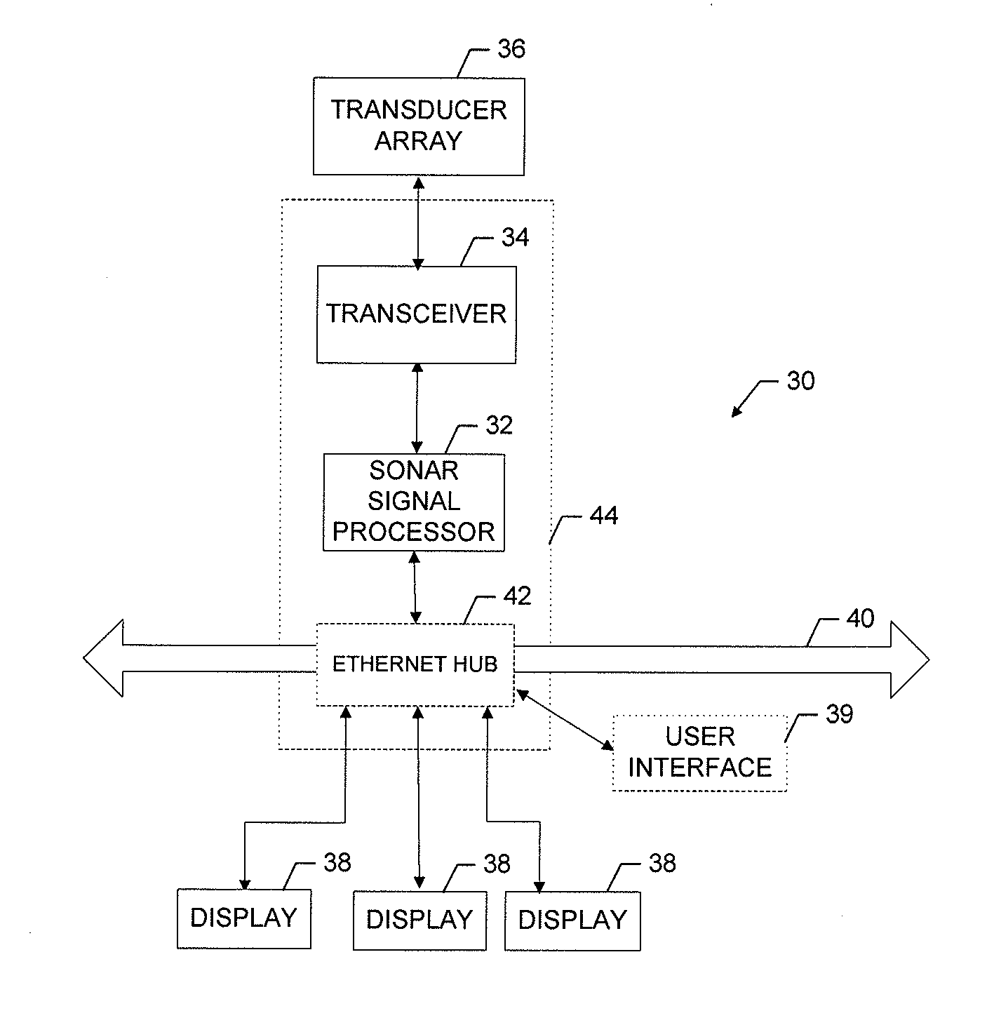
[0052]FIG. 5 is a basic block diagram illustrating a sonar system 30 for use with multiple exemplary embodiments of the present invention. As shown, the sonar system 30 may include a number of different modules or components, each of which may comprise any device or means embodied in either hardware, software, or a combination of hardware and software configured to perform one or more corresponding functions. For example, the sonar system 30 may include a sonar signal p...


PUM

PropertyMeasurementUnit
operating frequencyaaaaaaaaaa
widthaaaaaaaaaa

Abstract

A sonar transducer assembly for mounting to a surface watercraft includes a rectangular first transducer configured to produce a first beam defining a fan-shape and extending generally in a first plane. The assembly further includes a rectangular second transducer configured to produce a second beam defining a fan-shape and extending generally in a second plane. The first transducer and the second transducer are oriented such that the respective first and second beams insonify different first and second areas each extending laterally with respect to a running direction of the surface watercraft, and such that the first beam is outside of the second plane of the second beam, the resulting planar separation of the first and second planes of the first and second beams reducing interference between the first and second transducers.

Description

RELATED APPLICATION[0001]The present invention is a Continuation of U.S. patent application Ser. No. 12 / 460,139, filed Jul. 14, 2009, entitled “Downscan Imaging Sonar,” which is incorporated by reference in its entirety.FIELD OF THE INVENTION[0002]Embodiments of the present invention relate generally to sonar systems, and more particularly, to providing a downscan imaging sonar using a linear transducer.BACKGROUND OF THE INVENTION[0003]Sonar has long been used to detect waterborne or underwater objects. For example, sonar devices may be used to determine depth and bottom topography, detect fish or other waterborne contacts, locate wreckage, etc. In this regard, due to the extreme limits to visibility underwater, sonar is typically the most accurate way for individuals to locate objects underwater. Devices such as transducer elements, or simply transducers, have been developed to produce sound or vibrations at a particular frequency that is transmitted into and through the water and ...

Claims


Application Information

Patent Timeline
Patent Type & Authority Applications(United States)
IPC IPC(8): G01S15/89B23P11/00
CPCG01S15/89G01S15/96G01S15/8902Y10T29/49826G01S7/56
Inventor MAGUIRE, BRIAN T.
Owner NAVICO HLDG
Why Eureka
Try Eureka