Low permeability airbag cushions having extremely low coating levels

Inactive Publication Date: 2009-04-14
MILLIKEN & CO
View PDF2 Cites 16 Cited by
  • Summary
  • Abstract
  • Description
  • Claims
  • Application Information

AI Technical Summary

Benefits of technology

[0016]It is understood that the 10 psi constant is not a limitation to the invention; but merely the constant pressure at which the leak-down time measurements are made. Thus, even if the pressure is above or below this amount during actual inflation or after initial pressurizing of the airbag, the only limitation is that if one of ordinary skill in the art were to measure the bag volume and divide that by the volumetric leakage rate (measured by the amount leaking out of the target airbag during steady state inflation at 10 psi), the resultant measurement in time would be at least 5 seconds. Preferably, this time is greater than about 9 seconds; more preferably, greater than about 15 seconds; and most preferably, greater than about 20 seconds.
[0017]Alternatively, and in a manner of measurement with uninflated side curtain airbags, the term “leak-down time” may be measured as the amount of time required for at half of the introduced inflation gas to escape from the target airbag after initial peak pressure is reached. Thus, this measurement begins the instant after peak initial pressure is reached upon inflation (such as, traditionally, about 30 psi) with a standard inflation module. It is well understood that the pressure of gas forced into the airbag after peak initial pressure is reached will not remain stable (it decreases during the subsequent introduction of inflation gas), and that the target airbag will inevitably permit escape of a certain amount of inflation gas during that time. The primary focus of such side curtain airbags (as noted above) is to rema

Problems solved by technology

Such a coated low permeability airbag must provide a necessarily

Method used


Image

  • Low permeability airbag cushions having extremely low coating levels
  • Low permeability airbag cushions having extremely low coating levels
  • Low permeability airbag cushions having extremely low coating levels

Examples


Example

DETAILED DESCRIPTION OF THE DRAWINGS

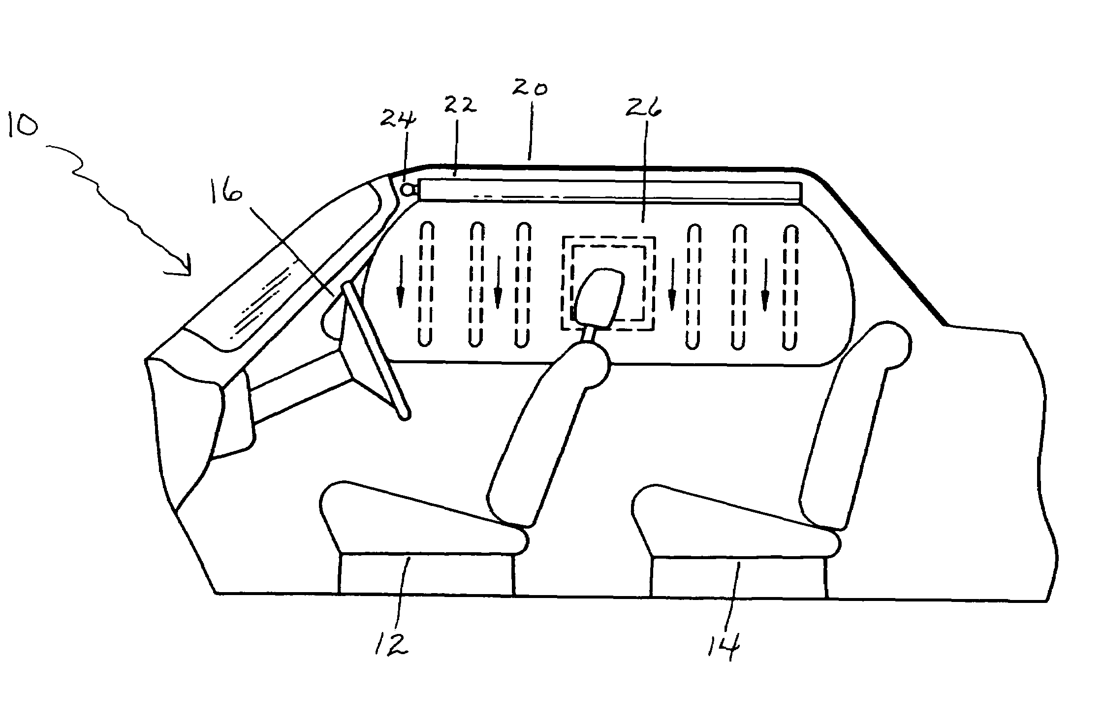
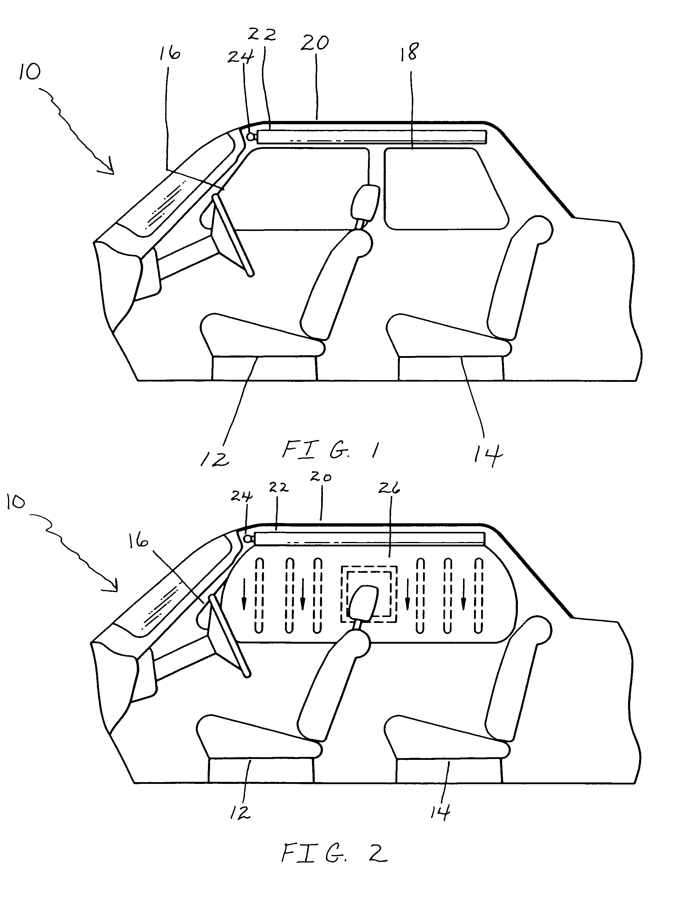
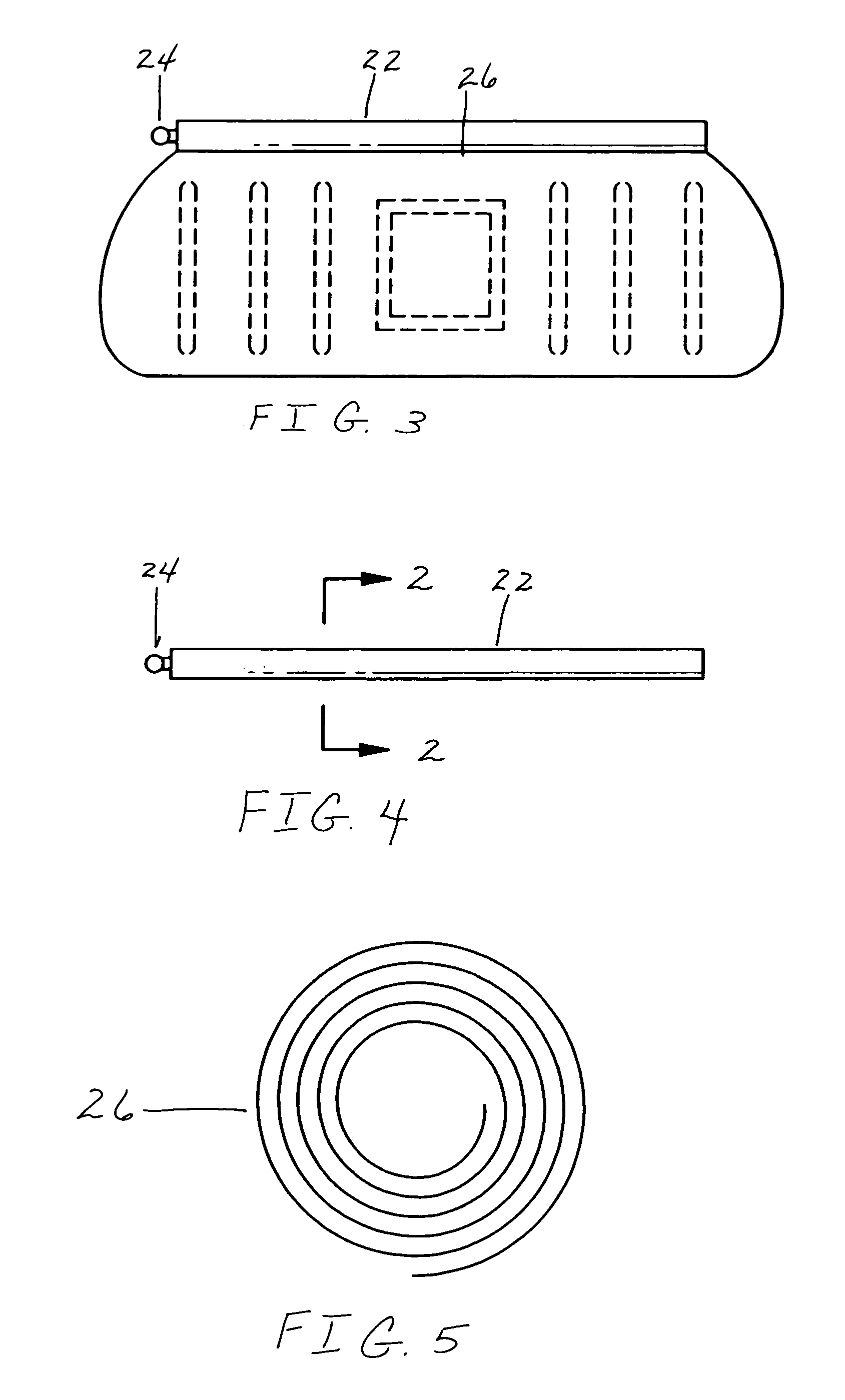
[0053]As depicted in FIG. 1, an interior of a vehicle 10 prior to inflation of a side curtain airbag (not illustrated) is shown. The vehicle 10 includes a front seat 12 and a back seat 14, a front side window 16 and a back-side window 18, a roofline 20, within which is stored a cylindrically shaped container 22 comprising the inventive side curtain airbag (not illustrated). Also present within the roofline 20 is an inflator assembly 24 which ignites and forces gas into the side curtain airbag (26 of FIG. 2) upon a collision event.

[0054]FIG. 2 shows the inflated side curtain airbag 26. As noted above, the airbag 26 is coated with at most 2.5 ounces per square of a coating formulation (not illustrated), preferably polyurethane polycarbonate. The inventive airbag 26 will remain sufficiently inflated for at least 5 seconds, and preferably more, as high as at least 20 seconds, most preferably.

[0055]FIG. 3 shows the side curtain airbag 26 prior to stora...


PUM

PropertyMeasurementUnit
Fractionaaaaaaaaaa
Fractionaaaaaaaaaa
Timeaaaaaaaaaa

Abstract

Coated inflatable fabrics, more particularly airbags to which very low add-on amounts of coating have been applied, are provided which exhibit extremely low air permeabilities. The inventive fabrics are primarily for use in automotive restraint cushions which require low permeability characteristics (such as side curtain airbags). Traditionally, heavy, and thus expensive, coatings of compounds such as neoprene, silicones and the like, have been utilized to provide such required low permeability. The inventive fabric utilizes an inexpensive, very thin coating to provide such necessary low permeability levels. Thus, the inventive coated airbag possesses a coating of at most 2.5 ounces per square yard, most preferably about 0.8 ounces per square yard, and exhibits a leak-down time (a measurement of the time required for the entire amount of gas introduced within the airbag at peak pressure during inflation to escape the airbag at 10 psi) of at least 7 seconds. All coatings, in particular elastomeric, non-silicon coatings, and coated airbags, meeting these criteria are intended to reside within the scope of this invention.

Description

CROSS REFERENCE TO RELATED APPLICATIONS[0001]This application is a continuation-in-part of application Ser. No. 09 / 350,620, filed on Jul. 9, 1999, now U.S. Pat. No. 6,177,366, which is a continuation-in-part of Ser. No. 09 / 335,257, filed on Jun. 17, 1999, now U.S. Pat. No. 6,177,365. These parent applications are herein entirely incorporated by reference.FIELD OF THE INVENTION[0002]This invention relates generally to coated inflatable fabrics and more particularly concerns airbag cushions to which very low add-on amounts of coating have been applied and which exhibit extremely low air permeability. The inventive inflatable fabrics are primarily for use in automotive restraint cushions that require low permeability characteristics (such as side curtain airbags). Traditionally, heavy, and thus expensive, coatings of compounds such as neoprene, silicones and the like, have been utilized to provide such required low permeability. The inventive fabric utilizes an inexpensive, very thin c...

Claims


Application Information

Patent Timeline
IPC IPC(8): B29D22/00
CPCB60R21/235D06N3/10D06N3/14D06M15/564B60R21/232B60R2021/23514Y10T428/1362Y10T442/2893Y10T442/2049Y10T442/2164Y10T442/3366
Inventor LI, SHULONGSOLLARS, JR., JOHN A.
Owner MILLIKEN & CO
Why Eureka
Try Eureka