Current-triggered low turn-on voltage SCR

a low turn-on voltage and current-triggered technology, applied in the direction of semiconductor devices, semiconductor/solid-state device details, electrical apparatus, etc., can solve the problem of parasitic silicon-controlled rectifiers

Active Publication Date: 2009-04-14
MELLANOX TECHNOLOGIES LTD
View PDF4 Cites 94 Cited by
  • Summary
  • Abstract
  • Description
  • Claims
  • Application Information

AI Technical Summary

Problems solved by technology

Preferably, the silicon controlled rectifier is parasitic.

Method used


Image

  • Current-triggered low turn-on voltage SCR
  • Current-triggered low turn-on voltage SCR
  • Current-triggered low turn-on voltage SCR

Examples


Embodiment Construction

[0020]The present invention is of a system and method, for protecting integrated circuits from ESD, that can be implemented with minimal real estate requirements, that introduces very little parasitic capacitance and that does not require serial resistance or additional NMOS devices.

[0021]The principles and operation of ESD protection according to the present invention may be better understood with reference to the drawings and the accompanying description.

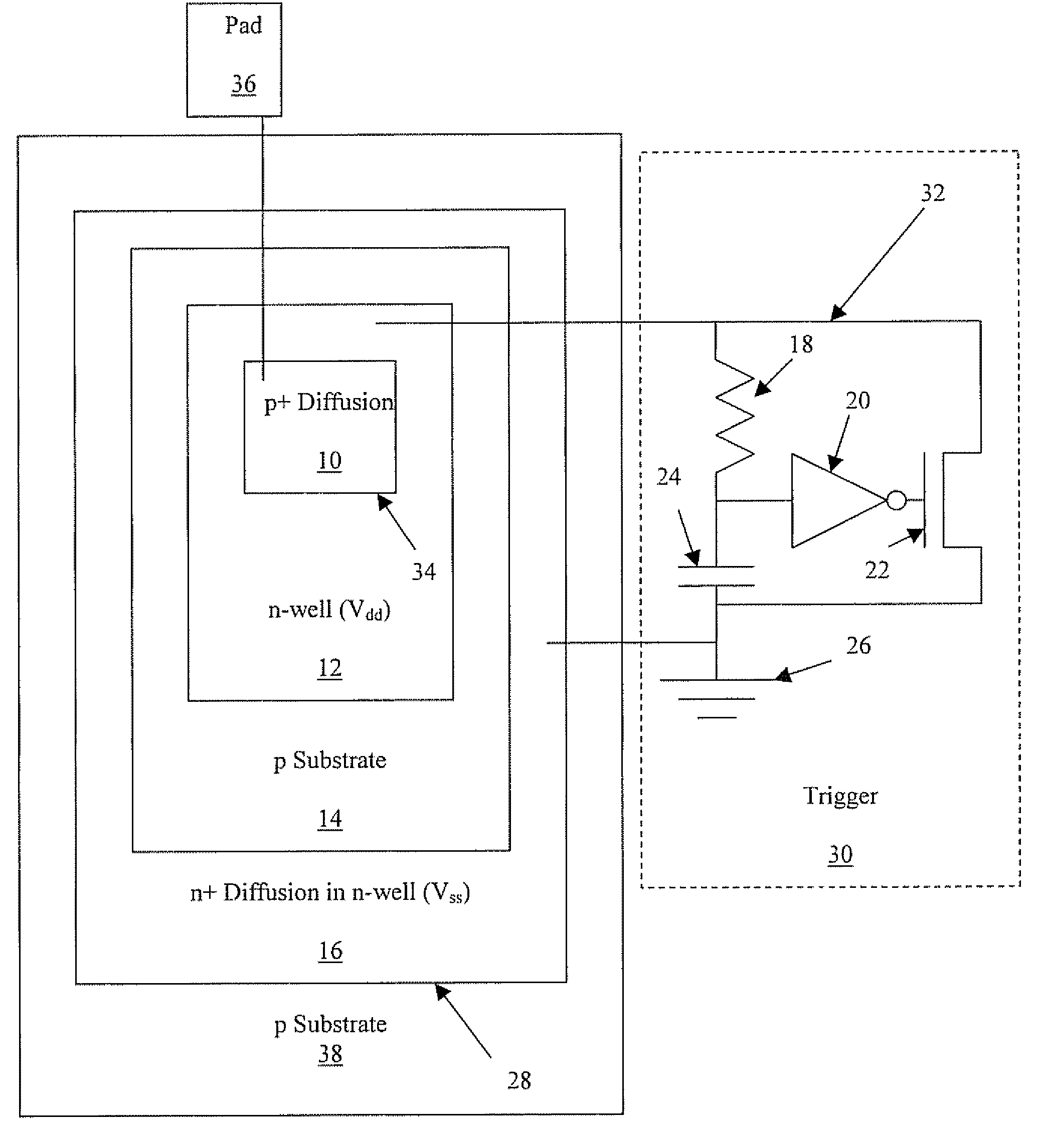
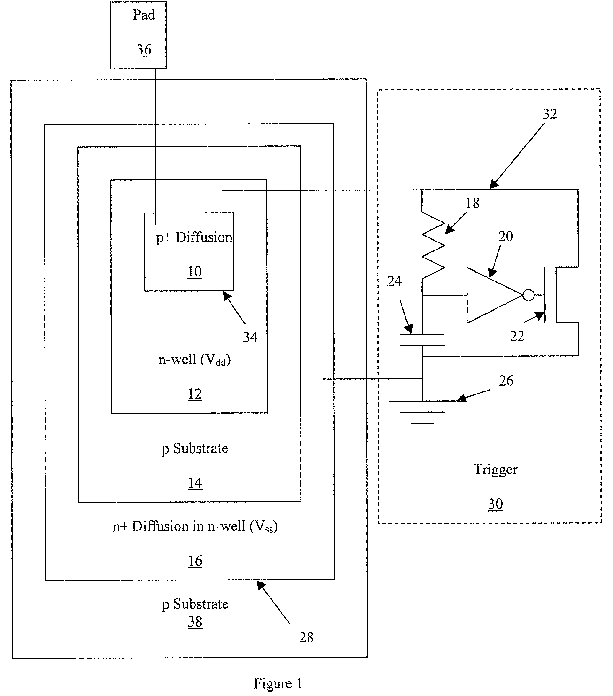
[0022]Referring now to the drawings, FIG. 1 illustrates schematically a layout of a preferred embodiment of the present invention wherein ESD protection is provided to an I / O pad 36 by an intrinsic parasitic SCR 28 triggered by a triggering circuit 30 indicated in FIG. 1 by a dashed box. Triggering circuit 30 is a preferred embodiment of the “triggering mechanism” of the appended claims. Superior ESD protection is afforded by providing low-voltage triggering of parasitic SCR 28, the triggering voltage being on the order of 1.2 Vol...


PUM


Abstract

A system for protecting a high-speed input / output pad of an integrated circuit. The system includes a preferably parasitic silicon controlled rectifier (SCR) and a triggering mechanism that preferably includes an NMOS triggering FET. The SCR includes an anode connected to the input / output pad and a trigger input. The anode and the trigger input form a reverse-biased junction that, during normal operation of the integrated circuit, isolates the triggering mechanism from the input / output pad when power is applied to the integrated circuit.

Description

[0001]This is a continuation-in-part of U.S. Provisional Patent Application Ser. No. 60 / 786,732, filled Mar. 29, 2006FIELD AND BACKGROUND OF THE INVENTION[0002]The present invention relates to a system and method for protecting integrated circuits from electrostatic discharge (ESD) and, more particularly, to the firing of a silicon controlled rectifier (SCR), operative to provide a safe discharge path for the ESD current, via a low-voltage triggering mechanism. High speed input / output (I / O) buffers transmitting signals at data rates higher than 5 Gbps incorporate semiconductor devices having oxides as thin as 20-30 Angstrom. These oxides must be protected from ESD. In order not to diminish the electronic performance of these I / O buffers the ESD protection must introduce very little parasitic capacitance or serial resistance. The present invention presents an ESD protection solution that meets these requirements by utilizing a current-triggered low turn-on voltage parasitic SCR intri...

Claims


Application Information

Patent Timeline
Patent Type & Authority Patents(United States)
IPC IPC(8): H01L23/60
CPCH01L27/0262H01L2924/0002H01L2924/00
Inventor SMELLOY, YOSSIECKHOUSE, RONENFROST, EYAL
Owner MELLANOX TECHNOLOGIES LTD
Why Eureka
Try Eureka