LED lighting device and LCD device using the same
a technology of lighting devices and drive circuits, applied in lighting and heating apparatus, process and machine control, instruments, etc., can solve the problems of increasing circuit costs, increasing the number of photo sensors, and difficulty in compensating brightness fluctuations, etc., and achieve stable luminance
- Summary
- Abstract
- Description
- Claims
- Application Information
AI Technical Summary
Benefits of technology
Problems solved by technology
Method used
Image
Examples
embodiment 1
[0041]Detailed explanation will be given on the first embodiment of the present invention with reference to FIGS. 1 to 8.
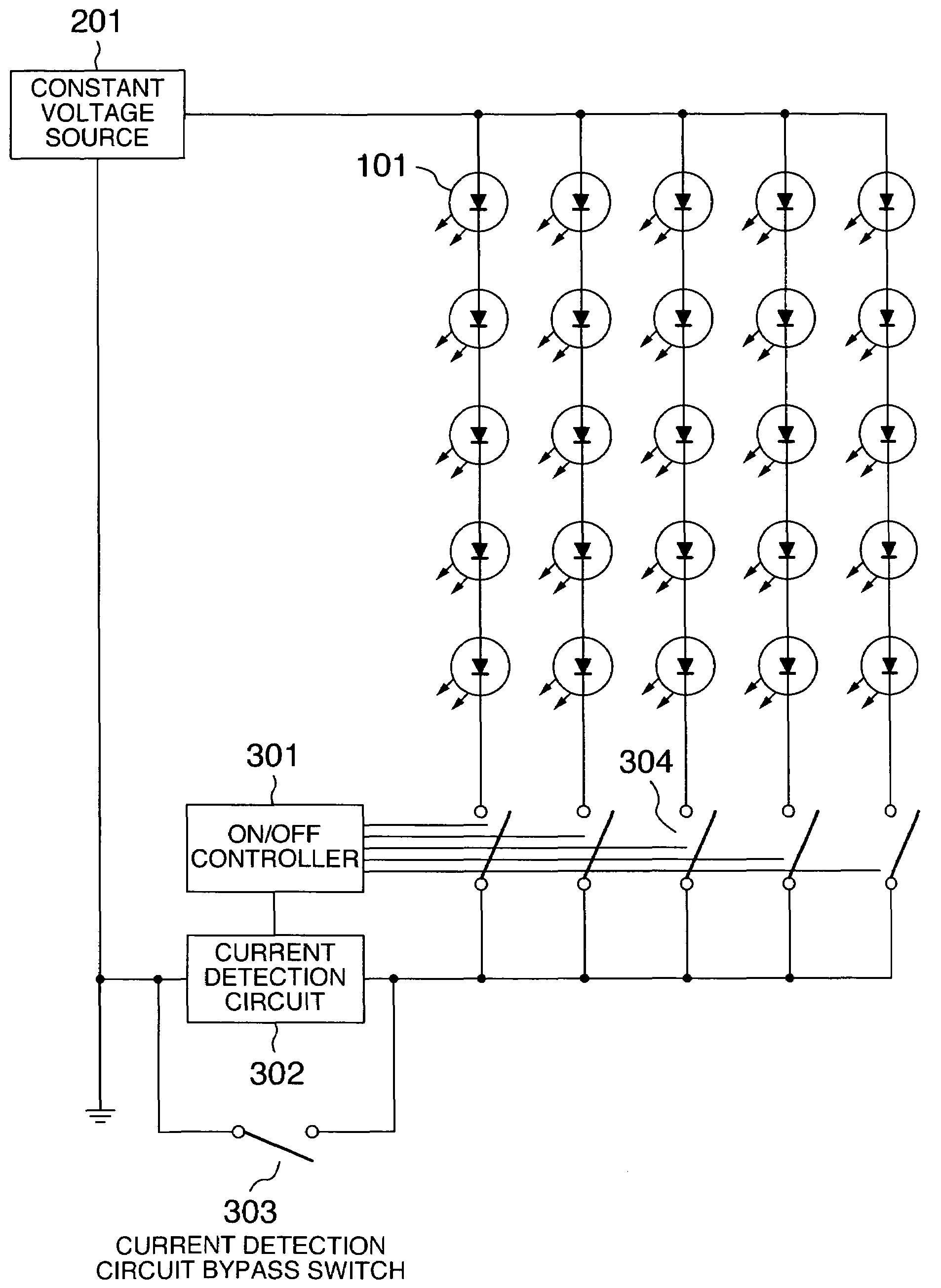
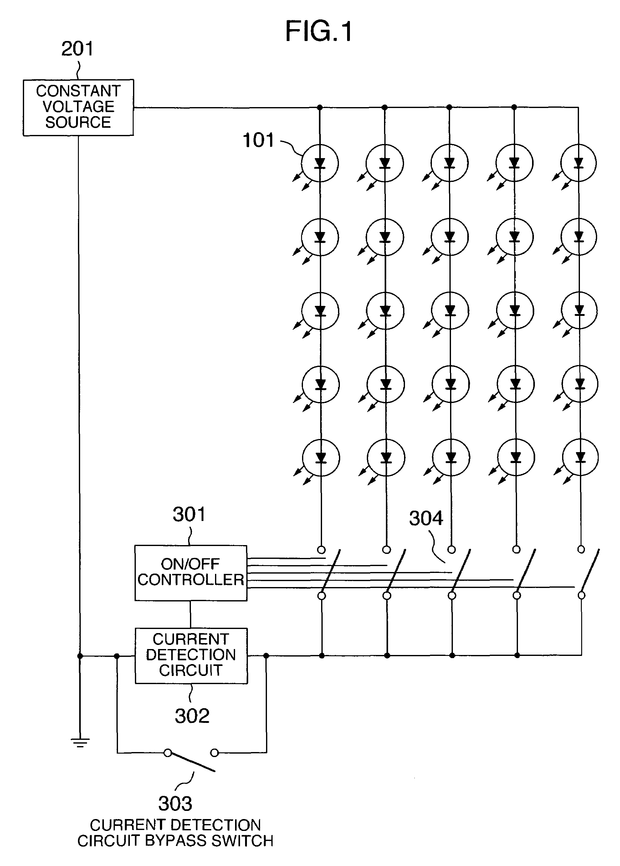
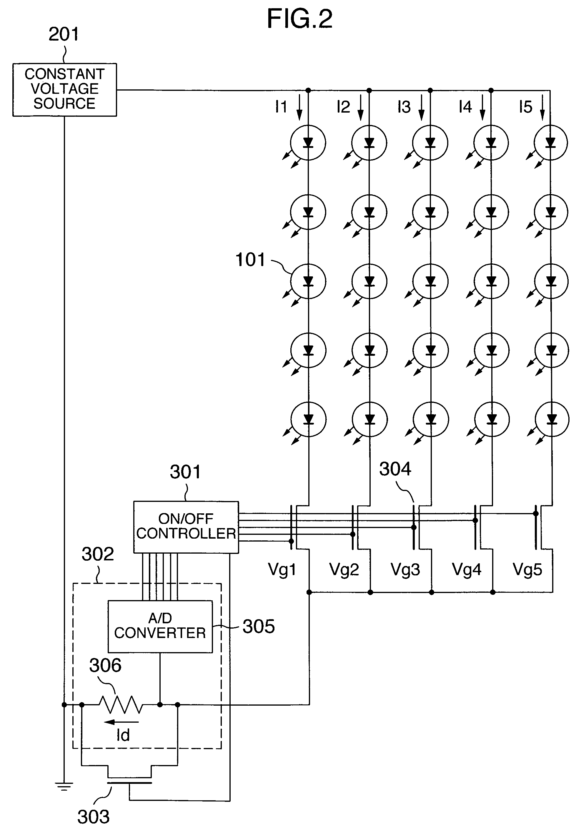
[0042]FIG. 1 shows a concept of a circuit configuration according to the present embodiment. The present embodiment uses five lines, each including five LEDs 101 connected in series and a switch 304 connected in series to the LEDs. The five lines are connected in parallel and each line is driven by a constant voltage source 201.
[0043]A current detector 302 and a bypass switch 303 are arranged at a portion where currents of all the lines are concentrated. With this configuration, it is possible to measure the current values of all the lines by the single current detector 302. That is, only the switch 304 of the line whose current value is to be detected is turned ON and the current flow is measured by the current detector 302. Thus, it is possible to measure a current value of each line.
[0044]Moreover, when no current is to be measured, the bypass switch 303 is tur...
embodiment 2
[0058]Explanation will be given on the second embodiment of the present invention.
[0059]The explanation will be given by referring to FIG. 9.
[0060]The present embodiment shows 12 lines connected in parallel. Each of the lines is connected to an LED 101 and a switch 304 in series. These lines are driven by a constant voltage source 201. The switch 304 of each line is controlled to be ON / OFF by an ON / OFF controller 301. Moreover, the current detector 302 and the bypass switch 303 are arranged in parallel at a position where currents of all the lines are concentrated.
[0061]Furthermore, temperature detection means 310 is provided. A condition table 307 built in the ON / OFF controller 301 decides the ON / OFF period of each line according to the current value of each line and the detection result of the temperature detection means 310.
[0062]By detecting the current of each line, it is possible to adjust the ON / OF period ratio of each line to compensate the brightness fluctuation in the same...
embodiment 3
[0066]Explanation will be given on the third embodiment of the present invention with reference to FIG. 10 and FIG. 11.
[0067]FIG. 10 shows a circuit configuration of the present embodiment. The AC power input is amplified by a transformer 311 and subjected to a rectifier circuit 312 and a smoothing circuit 313 so as to generate a constant voltage. The voltage is adjusted by a switching regulator 314 and used as a constant voltage source 201 of green (G) and blue (B). The G and B voltages are reduced by a step down chopper and the voltage is used as a constant voltage source 201 of red (R). Thus, a plurality of primary colors share the constant voltage source 201, thereby reducing the power cost.
[0068]In this embodiment, three LEDs are connected in series for each of the primary colors and the switch 304 is connected in series in each line. Moreover, two lines are connected in parallel for each of the primary colors.
[0069]The low potential side of each line is commonly connected and ...
PUM
 Abstract
Description
Claims
Application Information
 - R&D
- Intellectual Property
- Life Sciences
- Materials
- Tech Scout
- Unparalleled Data Quality
- Higher Quality Content
- 60% Fewer Hallucinations
Browse by: Latest US Patents, China's latest patents, Technical Efficacy Thesaurus, Application Domain, Technology Topic, Popular Technical Reports.
© 2025 PatSnap. All rights reserved.Legal|Privacy policy|Modern Slavery Act Transparency Statement|Sitemap|About US| Contact US: help@patsnap.com


