Magnetic head tester and method of manufacturing magnetic disk drive

a magnetic disk drive and tester technology, applied in the field of magnetic disk drive manufacturing, can solve the problems of unsolved problems in document 1 in changing the hga, problems to be solved, and the magnetic disk testing apparatus mentioned, and achieve the effect of accurate servo pattern, small shift of disk center, and small synchronization

Inactive Publication Date: 2009-04-14
HITACHI GLOBAL STORAGE TECH NETHERLANDS BV
View PDF27 Cites 6 Cited by
  • Summary
  • Abstract
  • Description
  • Claims
  • Application Information

AI Technical Summary

Benefits of technology

[0006]Accordingly, it is a first object of the present invention to achieve quickly and safely attaching an HGA to and quickly and safely removing the HGA from the arm of a VCM actuator. A fixing mechanism for fixing the HGA to the arm should be as light as possible to avoid obstructing servo operations of the arm by the VCM. It is desirable to attach the HGA to and remove the HGA from the arm by an automatic mechanism to avoid causing electrical and mechanical damage by manual operations.
[0016]The magnetic head tester of the present invention including many parts of a production HDD can be manufactured at a very low cost. Automatic HGA attaching and removing operation performed by the automatic machine improves operability and avoids causing electrical and mechanical damage by manual operations. Since the test uses a production card, the performance of the head of a production HDD can be more correctly evaluated. The abilities of the production HDD make remarkable progress with time and hence it is difficult for the conventional DET to cope with the progress. Improvements in production HDDs can be directly incorporated into the tester because the approach according to the present invention uses the production card.

Problems solved by technology

However, there are problems to be solved when such a DET based on known techniques is used as a magnetic head testing apparatus.
For example, the magnetic disk testing apparatus mentioned in Patent Document 1 has unsolved problems in changing the HGA.
Frequent change of the HGA by unfastening and fastening the screw is not desirable because productivity will be reduced and manual changing of the HGA is likely to cause electrical and mechanical damage.
It is possible that the actuator runs away when an excessively high current is supplied accidentally to the coil due to defective servo information.
However, the tester of the present invention performs special servo operations specific to the tester and hence the servomechanism of a practical HDD cannot be employed without alteration.

Method used


Image

  • Magnetic head tester and method of manufacturing magnetic disk drive
  • Magnetic head tester and method of manufacturing magnetic disk drive
  • Magnetic head tester and method of manufacturing magnetic disk drive

Examples


embodiment 1

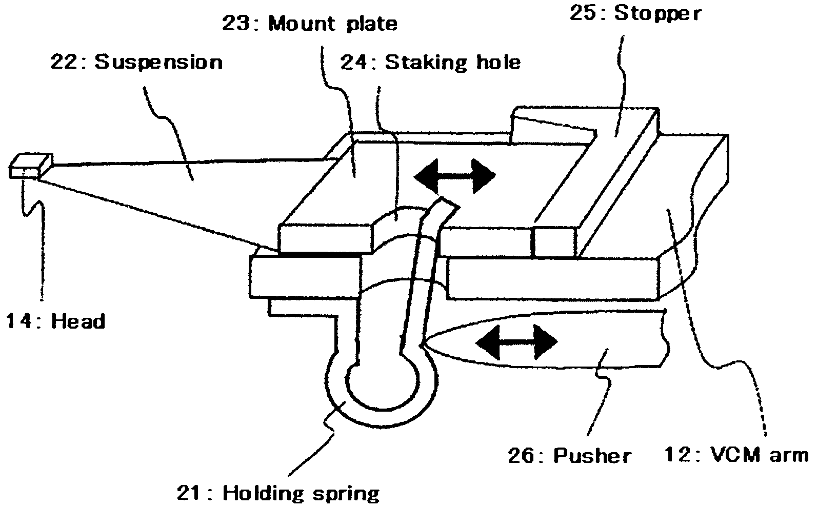
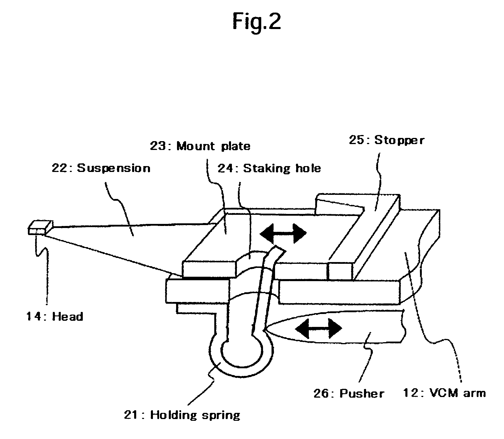
[0029]A magnetic head tester in Embodiment 1 uses a holding spring 21 for holding an HGA in place as shown in FIG. 2. The holding spring 21 has a first end part fixed to a lower part of the VCM arm 12 and a second end part pressed against one side of a staking hole 24 formed in an HGA mount plate 23 included in the HGA. This spring force is applied to the HGA. The holding spring 21 presses the HGA mount plate 23 elastically against a stopper 25. To remove the HGA from the VCM arm 12, a pusher 26 included in the magnetic head tester is brought into engagement with a curved part of the holding spring 21 and pushes the curved part of the holding spring 21 to the left, as viewed in FIG. 2, to separate the second end part of the holding spring 21 from the side of the staking hole 24. The HGA thus released from the holding spring 21 can be attached to and removed from the VCM arm 12 by a simple pick & place operation.

[0030]FIG. 3 shows an HGA positioning structure. The HGA is positioned o...

embodiment 2

[0032]FIG. 5 shows an HGA fixing mechanism that uses air pressure for fixing the HGA to the VCM arm 12 by way of example. FIGS. 5(a) and 5(b) show the HGA fixing mechanism in an HGA releasing condition and in an HGA fixing condition, respectively. In the HGA releasing condition, an air cylinder actuator 32 pushes up a clamping arm 31 to extend the clamping arm 31. The outside diameter of the thus extended clamping arm 31 is smaller than the diameter of the staking hole 24 formed in the mount plate 23. Therefore, the clamp plate 23 of the HGA can be removed from the extended clamping arm 31 by a pick & place operation. In the HGA fixing condition shown in FIG. 5(b), the air cylinder actuator 32 pulls down the clamping arm 31 so that lower arm members of the clamping arm 31 press the mount plate 23 against the VCM arm 12.

embodiment 3

[0033]FIG. 6 shows another HGA fixing mechanism in Embodiment 3 that uses air pressure for fixing the HGA to the VCM arm 12. FIGS. 6(a) and 6(b) show the HGA fixing mechanism in an HGA releasing condition and in an HGA fixing condition, respectively. This HGA fixing mechanism includes a clamping spring 41 instead of the clamping arm 31. Although this HGA fixing mechanism in Embodiment 3 is substantially the same as the HGA fixing mechanism in Embodiment 2 in the principle of operation, the clamping spring 41 is a single member while the clamping arm 31 has the four arm members. Thus, the HGA fixing mechanism in Embodiment 3 is very simple in construction.


PUM

PropertyMeasurementUnit
lengthaaaaaaaaaa
magnetic head testeraaaaaaaaaa
magnetic head testingaaaaaaaaaa

Abstract

Embodiments of the invention provide an inexpensive magnetic head tester employing component parts of a production HDD and capable of exercising functions very close to those of a production HDD. In one embodiment, a magnetic head tester employs the VCM actuator and the control circuit of a production HDD and has a lightweight, simple HGA fixing mechanism mounted on an actuator arm. The HGA fixing mechanism fixes an HGA to the actuator arm by a method using a very light holding spring mounted on the arm, a method of mechanically clamping an HGA by using air pressure, or a method of fixing an HGA to the arm by elastically deforming a rubber clamping member by air pressure. Servo control is achieved by the actuator of a production VCM. An end part of the VCM actuator is stopped by a stopping mechanism and is held by a holding spring to prevent the runaway of the VCM actuator. Servo control is performed by balancing the driving force of the VCM and the resilience of the spring.

Description

CROSS-REFERENCES TO RELATED APPLICATIONS[0001]This application claims priority from Japanese Patent Application No. JP2005-253272, filed Sep. 1, 2005, the entire disclosure of which is incorporated herein by reference.BACKGROUND OF THE INVENTION[0002]The present invention relates to a magnetic head testing method of testing and choosing a magnetic head for a magnetic disk drive or hard disk drive (abbreviated to “HDD”) and a method of manufacturing an HDD employing a chosen magnetic head.[0003]Choosing a good magnetic head is essential to ensure the satisfactory quality of an HDD and to manufacture HDDs at a high yield. Generally, a head gimbals assembly (abbreviated to “HGA”) built by assembling a magnetic head and gimbals is subjected to a dynamic electric test. In the dynamic electric test, parameters of the magnetic head including output, overwrite, resolution and track width are measured. Magnetic heads which are expected to operate satisfactorily in HDDs are chosen on the basi...

Claims


Application Information

Patent Timeline
Patent Type & Authority Patents(United States)
IPC IPC(8): G11B27/36
CPCG11B5/012G11B5/455G11B5/4555G11B2005/001
Inventor UMEZAKI, HIROSHIMIYAMOTO, NORIFUMIWASHIZU, KAZUHIKOHAMAGUCHI, TAKEHIKOITOH, KENJI
Owner HITACHI GLOBAL STORAGE TECH NETHERLANDS BV
Why Eureka
Try Eureka