Angular rate sensor featuring mechanically decoupled oscillation modes

a technology of angular rate sensor and oscillation mode, which is applied in the direction of speed measurement using gyroscopic effects, devices using electric/magnetic means, and automatic control of pulses, etc. it can solve the problem of direct impact on production costs, inability to tilt the primary oscillator, and inability to detect rotation motion about the same axis

Inactive Publication Date: 2009-04-21
LEONHARD OLGEMOELLER FRICKE +1
View PDF14 Cites 22 Cited by
  • Summary
  • Abstract
  • Description
  • Claims
  • Application Information

AI Technical Summary

Benefits of technology

[0012]a) If the drive oscillation is a rotation oscillation, the rotation speed affects the detection element in such a way that it begins a radial oscillation with the same frequency as the excitation oscillation fD due to the Coriolis force; (the disturbance sig

Problems solved by technology

While the secondary oscillator is then tilted out of its plane, the primary oscillator remains in this plane, because it is, on one hand, anchored on the substrate, making it nearly impossible for the primary oscillator to tilt out of this plane and, on the other hand, the torsion springs prevent the Coriolis force acting on the secondary oscillator to be coupled back to

Method used


Image

  • Angular rate sensor featuring mechanically decoupled oscillation modes
  • Angular rate sensor featuring mechanically decoupled oscillation modes
  • Angular rate sensor featuring mechanically decoupled oscillation modes

Examples


Embodiment Construction

[0023]The following designations will be used throughout the specification for oscillations and frequency:

vD, vD*: excitation (drive) oscillation, reference oscillation

fD, fD*: frequency of vD, vD*

f1: resonance frequency of this oscillating system

fD, fD* is generally selected so as to coincide with f1 for achieving the largest possible oscillation amplitude: fD=f1

vS: detection (sense) oscillation, measurement oscillation

fS: frequency of vS

f2: resonance frequency of this oscillating system

By matching the geometry, f2 is approximately equal to f1.

fMD: modulation frequency for measuring the reference oscillation

fMS: modulation frequency for measuring the measurement oscillation.

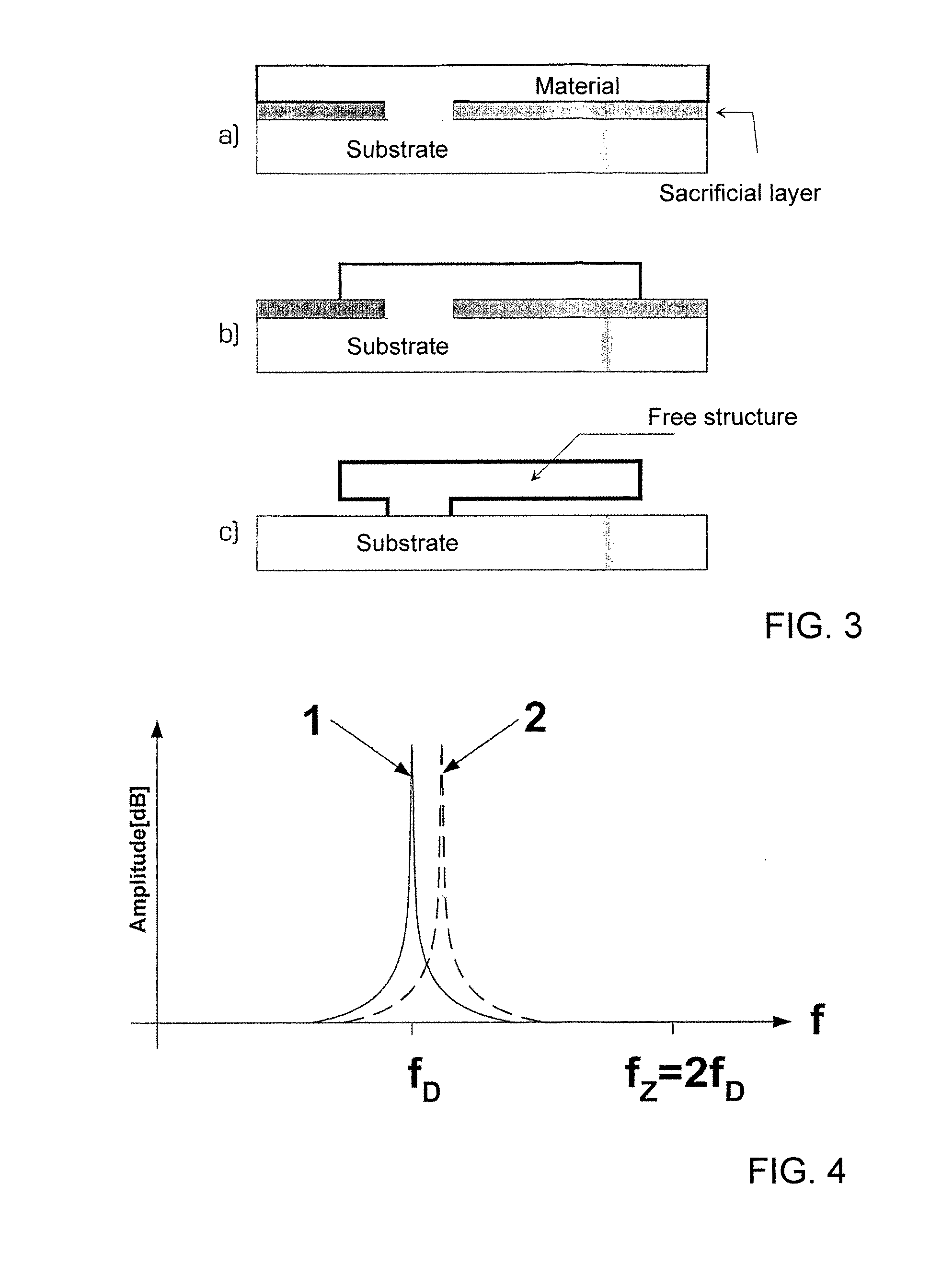
fZ: frequency of the (disturbance) oscillation produced by the centrifugal force.

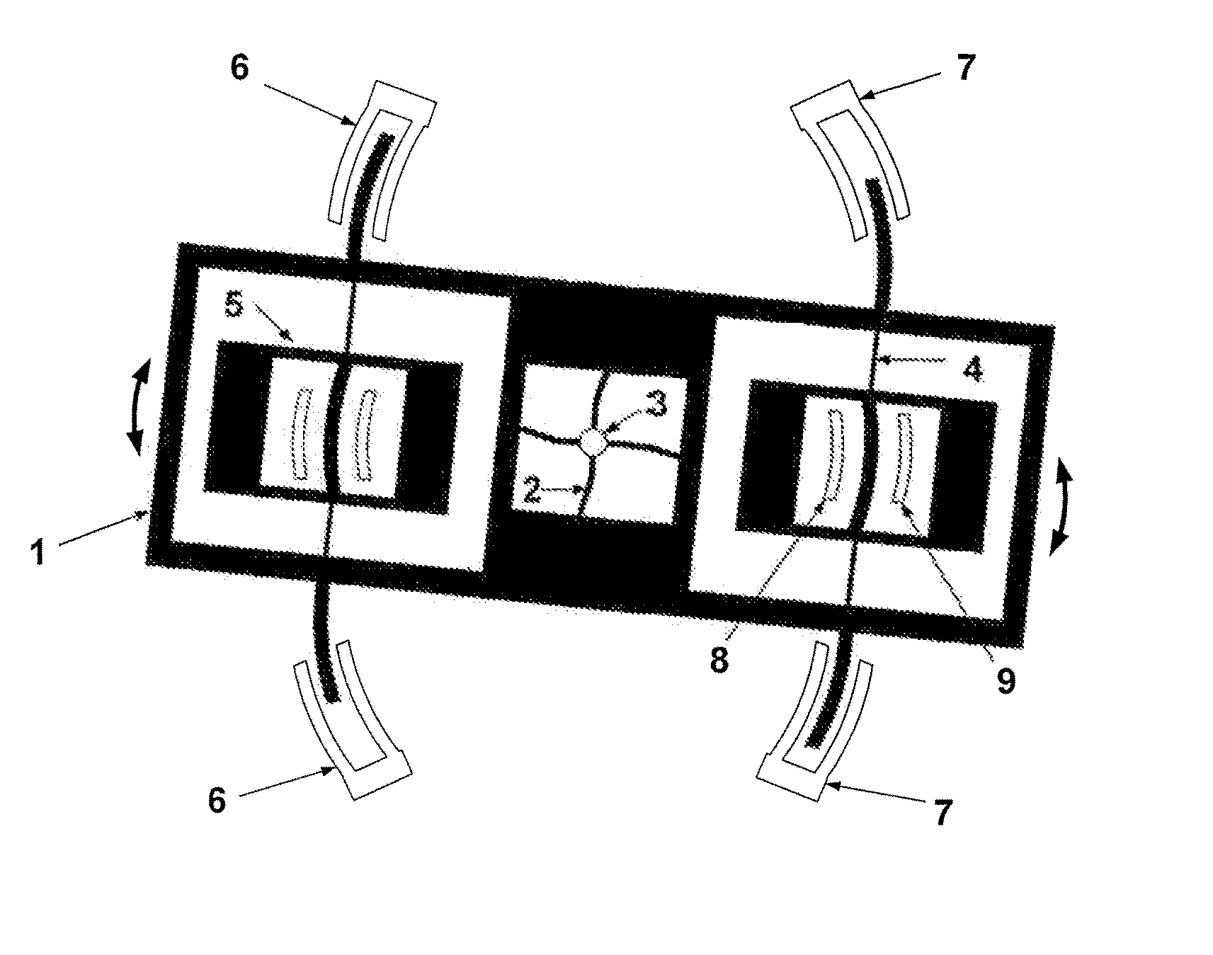
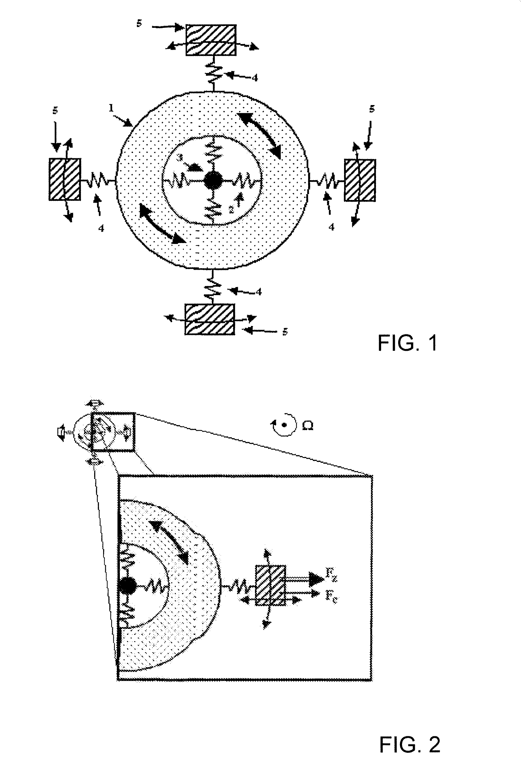
[0024]Exemplary embodiments of the present invention will now be described in more detail with reference to FIGS. 1 to 9. FIGS. 1 and 6 illustrate embodiments of the angular rate sensor of the invention. The sensor includes an osc...


PUM


Abstract

An angular rate sensor for detecting a rotation includes a substrate, at least one oscillating element that can be excited so as to oscillate rotationally or radially, an anchor structure, one or several detecting elements, one or several joining elements that connect the detecting element/s to the oscillating element, a mechanism for exciting the oscillating element, and a device for detecting a radial or rotational oscillation of the detecting element/s. Each of the detecting elements can oscillate radially on the same plane on which rotational oscillation of the oscillating element occurs, or vice versa, while the centrifugal force Fz caused by the rotational oscillation will not cause any significant radial movement of the detecting element/s or the oscillating elements. Also disclosed are different methods for operating said sensor.

Description

FIELD OF THE INVENTION[0001]The present invention relates to an angular rate sensor, in particular a micro-mechanical angular rate sensor for detecting a rotation by using the motion-induced Coriolis force.BACKGROUND OF THE INVENTION[0002]Micro-mechanical angular rate sensors (gyroscopes) are known in the art. They have been fabricated for some time on silicon wafers using conventional etching techniques. They can include a first element (primary oscillator, drive element) arranged in an x-y plane which is excited to perform an oscillatory motion, and a second element (secondary oscillator, output element) used for detection, which is connected with the first element via connecting elements. When the sensor performs a rotation motion Ω about an axis perpendicular to the oscillation axis, the Coriolis force of 2 m vr×u acts on the various masses of the body performing the rotation oscillation; this force is transferred by suitable measures to the detection element so as to deflect th...

Claims


Application Information

Patent Timeline
IPC IPC(8): G01C19/56G01P9/04
CPCG01C19/5712
Inventor SCHWARZELBACH, OLIVER
Owner LEONHARD OLGEMOELLER FRICKE
Why Eureka
Try Eureka