Angular rate sensor with suppressed linear acceleration response

a linear acceleration and angular rate sensor technology, applied in the direction of acceleration measurement using interia force, turn-sensitive devices, instruments, etc., can solve the problems of in-phase mode cannot be well suppressed, rate sensors are susceptible to linear acceleration, and the velocity of the mass is susceptible to linear acceleration in the drive direction, so as to improve the angular rate

Active Publication Date: 2013-06-04
MEMSLINK TECH CO LTD
View PDF7 Cites 53 Cited by
  • Summary
  • Abstract
  • Description
  • Claims
  • Application Information

AI Technical Summary

Benefits of technology

[0010]It is in general an object of the invention to provide a new and improved angular rate sensor or gyroscope.

Problems solved by technology

In general, a rate sensor can be susceptible to linear acceleration in the drive and sense directions of the proof masses of the sensor.
This parasitic mode allows the centroid of the proof masses to move in response to linear acceleration along the drive axis, so that the velocities of the masses are susceptible to linear acceleration in the drive direction.
However, the in-phase mode cannot be well suppressed due to the fact that the arcuate coupling member used is prone to bending and buckling under linear acceleration forces in the drive direction.
Furthermore, no actual gyroscope device utilizing that coupling method has been disclosed.
However, this coupling structure is complex which includes multiple levers, pivots, and flexures, and each proof mass has to split into two parts that move in arcuate motion, instead of pure linear movement.
The unbalanced arcuate motion of the two parts of a proof mass due to the process imperfections results in an undesired net movement of the masse in sense direction, which causes the error of the sensor.
Again, that linkage is complicated with requirement of multiple stiff rotation beams with inner anchor points as pivots that occupy a considerable layout area.
That makes it impossible to mount the linkage on movable structure, which is often desirable in multi-axes rate sensors.
The spurious sense signals caused by linear acceleration noise can only be cancelled when the two masses and their resonant frequencies of sense modes are identical, which are impractical due to the process imperfections.
And the un-cancelled residual signal becomes the error and noise in the rate signal.

Method used


Image

  • Angular rate sensor with suppressed linear acceleration response
  • Angular rate sensor with suppressed linear acceleration response
  • Angular rate sensor with suppressed linear acceleration response

Examples


Embodiment Construction

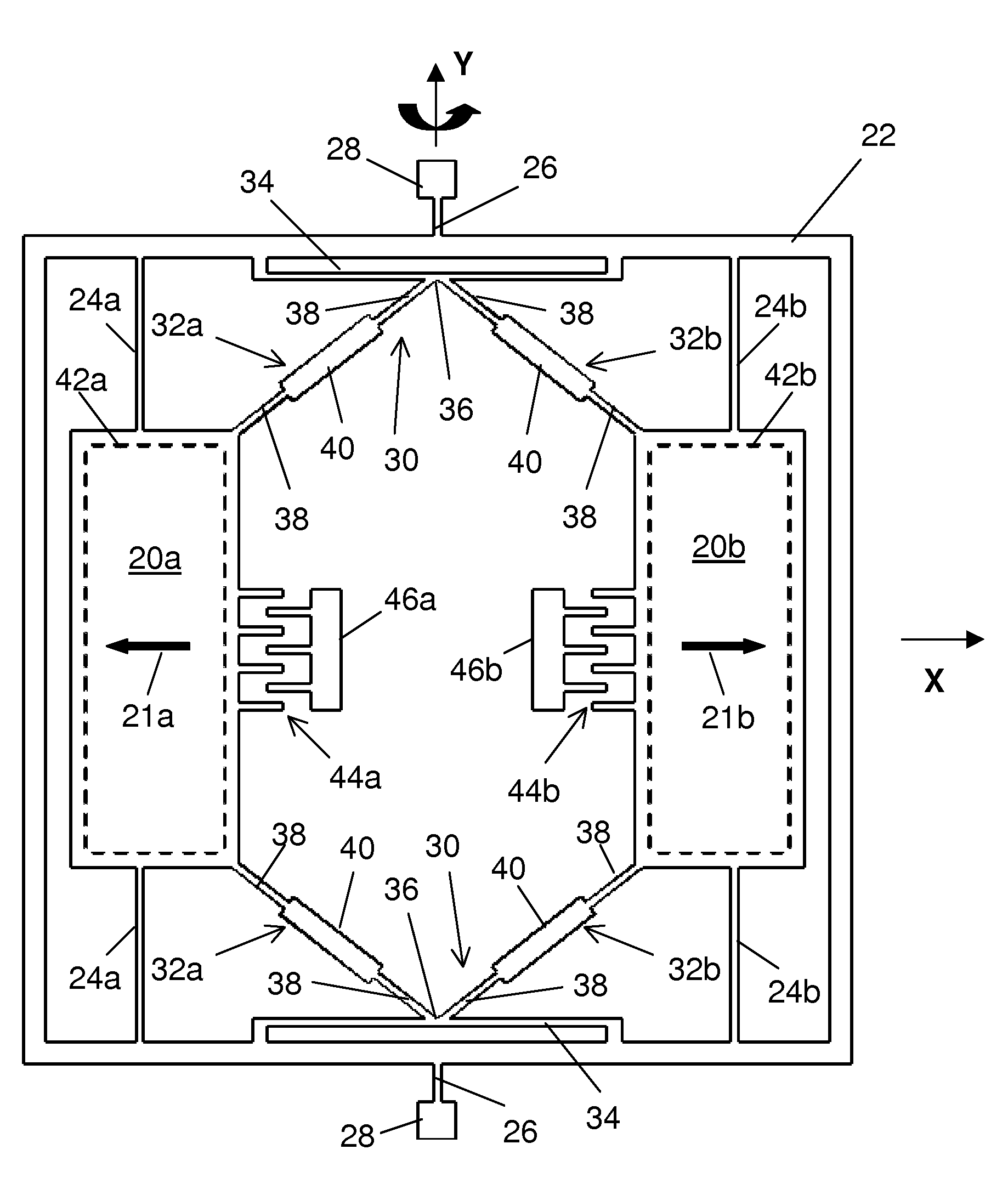
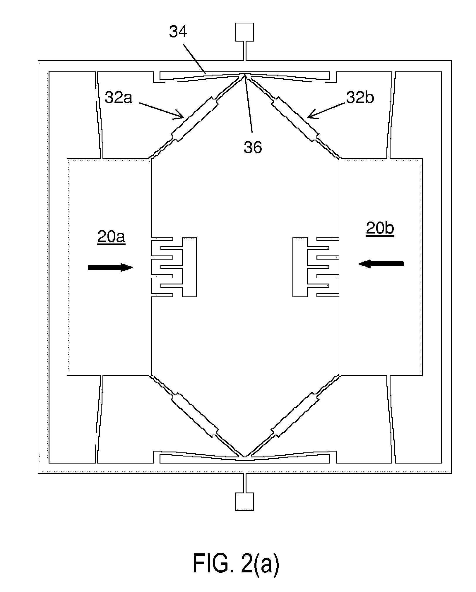
[0031]As illustrated in FIG. 1, the rate sensor has a pair of generally planar proof masses 20a, 20b that lie in an x, y reference plane when the device is at rest. The masses are disposed and spaced apart along the x-axis, which is the drive axis, i.e. the axis along which the masses are driven to oscillate in drive-mode. The input axis, i.e. the axis about which the angular rate of rotation is measured, is the y-axis.

[0032]The proof masses are suspended from a supporting frame, or sensing frame, 22 in the plane of the masses by flexible beams, or flexures, 24a, 24b. The flexures, which extend along the y-axis, are relatively flexible in the drive direction, but relatively stiff in other directions. These flexures constrain each one of the masses for linear movement along the x-axis.

[0033]The masses can be driven into oscillation along the drive axis by comb drives 44a, 44b, which have interdigitated comb fingers with moveable fingers attached to masses 20a, 20b and stationary fing...


PUM


Abstract

An angular rate sensor having two generally planar proof masses, a drive axis in the plane of the masses, and an input axis perpendicular to the drive axis. The masses are suspended from a sensing frame and constrained for anti-phase movement along the drive axis in drive-mode. The sensing frame is mounted for torsional movement in sense-mode about the input axis in response to Coriolis forces produced by rotation of the masses about the input axis, with sensors responsive to the torsional movement of the sensing frame and the masses about the input axis for monitoring rate of rotation.

Description

BACKGROUND OF THE INVENTION[0001]1. Field of Invention[0002]This invention pertains generally to micromachined angular rate sensors or gyroscopes, and more particularly to vibratory rate sensors utilizing dual-mass anti-phase translational movement in drive or sense modes.[0003]2. Related Art[0004]Many applications in automotive and consumer market require rate sensors to be insensitive to linear acceleration in all directions. In general, a rate sensor can be susceptible to linear acceleration in the drive and sense directions of the proof masses of the sensor.[0005]For rate sensors utilizing translational drive motion, commonly used dual-mass approach with conventional coupling method, such as that disclosed in U.S. Pat. No. 5,895,850, has an in-phase linear vibration mode with resonant frequency below that of the anti-phase drive-mode. This parasitic mode allows the centroid of the proof masses to move in response to linear acceleration along the drive axis, so that the velocitie...

Claims


Application Information

Patent Timeline
Patent Type & Authority Patents(United States)
IPC IPC(8): G01C19/00G01P3/44
CPCG01C19/56G01C19/574
Inventor MAO, MINYAO
Owner MEMSLINK TECH CO LTD
Why Eureka
Try Eureka