Determining Heading Using Magnetometer Data and Angular Rate Data

Active Publication Date: 2011-10-06
APPLE INC
View PDF2 Cites 53 Cited by
  • Summary
  • Abstract
  • Description
  • Claims
  • Application Information

AI Technical Summary

Benefits of technology

[0005]Sensor measurements are used to detect when a device incorporating the sensor is stationary. While the device is stationary, sensor measurements at a current device temperature are used to estimate model parameters. The model p

Problems solved by technology

The MEMS gyro is susceptible to bias, scale factor errors, and axis cross-sensitivities, as well as high frequency noise.
Cross-axis sensitivity is strongly affected by mounting stresses, while the magnitudes of the bias and scale fac

Method used


Image

  • Determining Heading Using Magnetometer Data and Angular Rate Data
  • Determining Heading Using Magnetometer Data and Angular Rate Data
  • Determining Heading Using Magnetometer Data and Angular Rate Data

Examples


Embodiment Construction

ters.

[0011]FIG. 4A illustrates an exemplary Cartesian coordinate system describing the Earth's geomagnetic field in accordance with some implementations.

[0012]FIG. 4B illustrates an exemplary 2-axis magnetometer in accordance with some implementations.

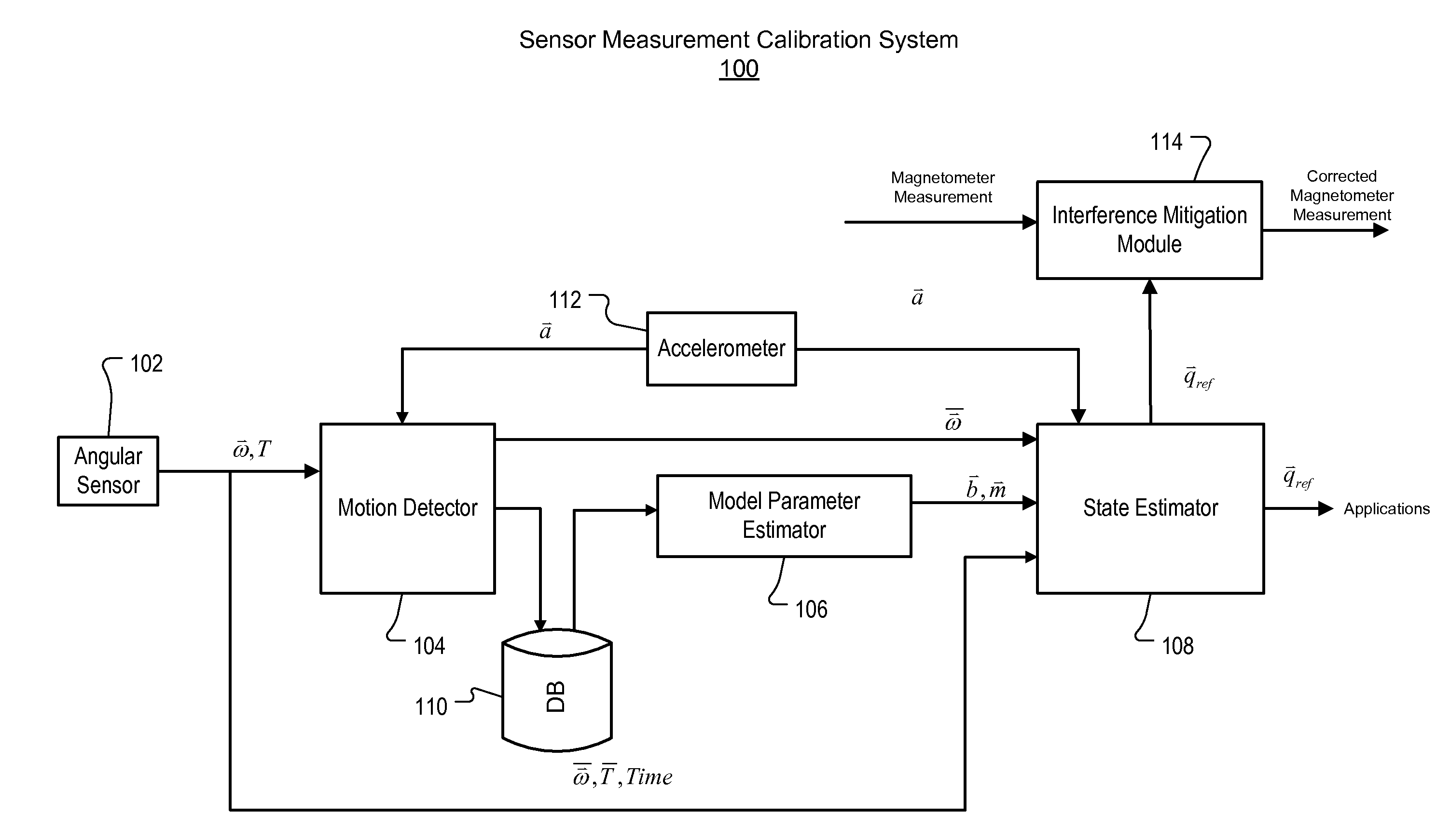
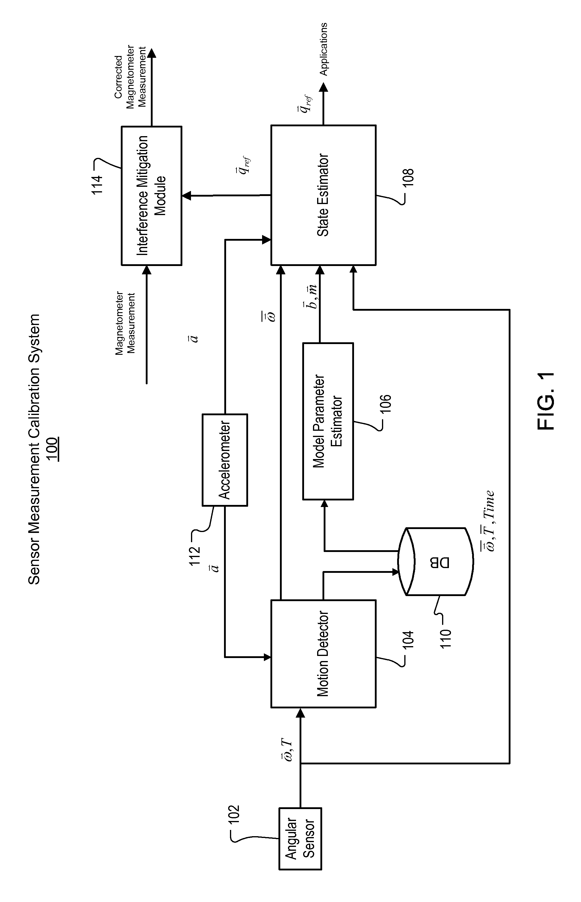
[0013]FIG. 4C is a block diagram of an exemplary system for determining heading using magnetometer data and angular rate data.

[0014]FIG. 4D is a flow diagram of an exemplary process of determining heading using magnetometer data and angular rate data.

[0015]FIG. 5 is a block diagram of an exemplary hardware architecture for implementing the system and processes referenced in FIGS. 1-4.

[0016]Like reference symbols in the various drawings indicate like elements.

DETAILED DESCRIPTION

Exemplary Sensor Measurement Calibration System

[0017]FIG. 1 is a block diagram of an exemplary sensor measurement calibration system 100. In some implementations, system 100 can include an angular rate sensor 102 (e.g., a MEMS gyro), motion detector 104, model p...


PUM


Abstract

A device coupled with a magnetometer and an angular rate sensor can determine a heading of the device using magnetometer data. When the device receives a notification that the magnetometer data may be inaccurate, the device can determine the heading of the device using angular rate data. When the device determines that the magnetometer data are accurate, the device can resume determining the heading of the device using the magnetometer data.

Description

CROSS-REFERENCE TO RELATED APPLICATIONS[0001]This application claims priority to pending U.S. Provisional Application Ser. No. 61 / 319,139, entitled “Calibrating Sensor Measurements on Mobile Devices”, filed on Mar. 30, 2010, and pending U.S. Provisional Application Ser. No. 61 / 356,550, entitled “Determining Heading Using Magnetometer Data and Angular Rate Data,” filed Jun. 18, 2010, the entire contents of each of which are hereby incorporated by reference.TECHNICAL FIELD[0002]This disclosure relates generally to determining a heading of a mobile device.BACKGROUND[0003]Angular rate sensors are used to measure the rotational velocity of an object without a fix point for referencing. A Micro-Electro-Mechanical System (MEMS) angular rate sensor (or MEMS gyro) can be incorporated into mobile devices due to its small size, weight and low cost. The principle of operation is based on the Coriolis effect. A MEMS resonator is driven at a certain frequency (e.g., about 10 kHz). Due to the angu...

Claims


Application Information

Patent Timeline
IPC IPC(8): G01B7/14
CPCG01C21/20G01C17/38G01C19/56G01C25/00G01P21/00
Inventor PIEMONTE, PATRICKMOORE, CHRISTOPHERKING, BRIAN MICHAELVIETA, WILLIAM MATTHEWTU, XIAOYUAN
Owner APPLE INC
Why Eureka
Try Eureka