Vibration type angular rate sensor

a technology of angular velocity sensor and vibration type, which is applied in the direction of acceleration measurement using interia force, turn-sensitive devices, instruments, etc., can solve the problems of insufficient voltage applied to the vibrator to reliably vibrate the vibrator, and inability to accurately detect the angular velocity signal. the accuracy of the wave detection is undetectable, so as to achieve high precision

Inactive Publication Date: 2005-12-15
DENSO CORP
View PDF7 Cites 57 Cited by
  • Summary
  • Abstract
  • Description
  • Claims
  • Application Information

AI Technical Summary

Benefits of technology

[0014] Therefore, because a level of the first clock signal is changed at a time differing from that in the second clock signal, the second clock signal is hardly deformed by noises generated during the generation of the first clock signal. Accordingly, synchronous detection

Problems solved by technology

Further, when the driving signal is set at a predetermined voltage level generally used in a control system, the voltage applied to the vibrator is insufficient to reliably vibrate the vibrator.
As a result,

Method used


Image

  • Vibration type angular rate sensor
  • Vibration type angular rate sensor
  • Vibration type angular rate sensor

Examples


embodiment

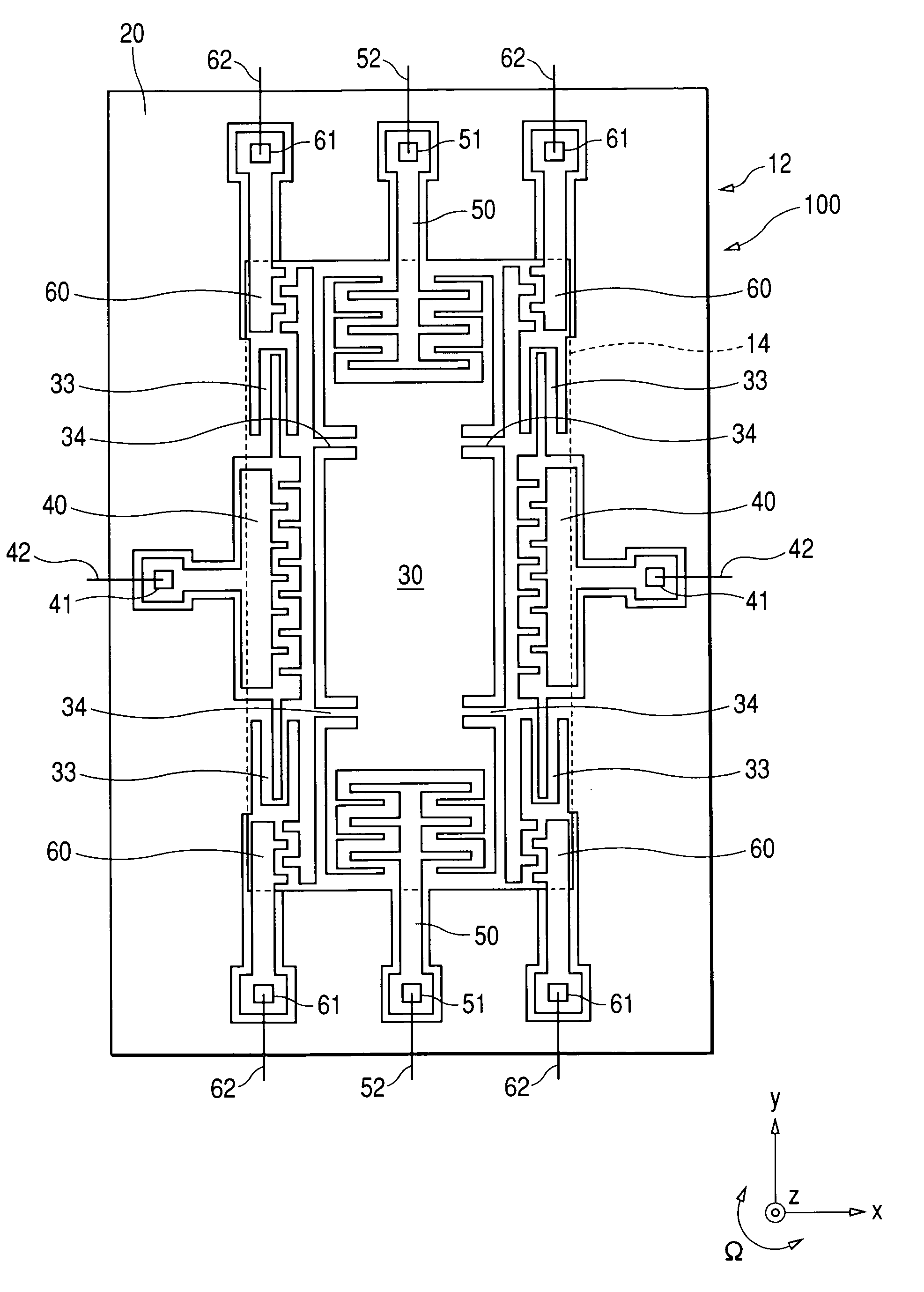
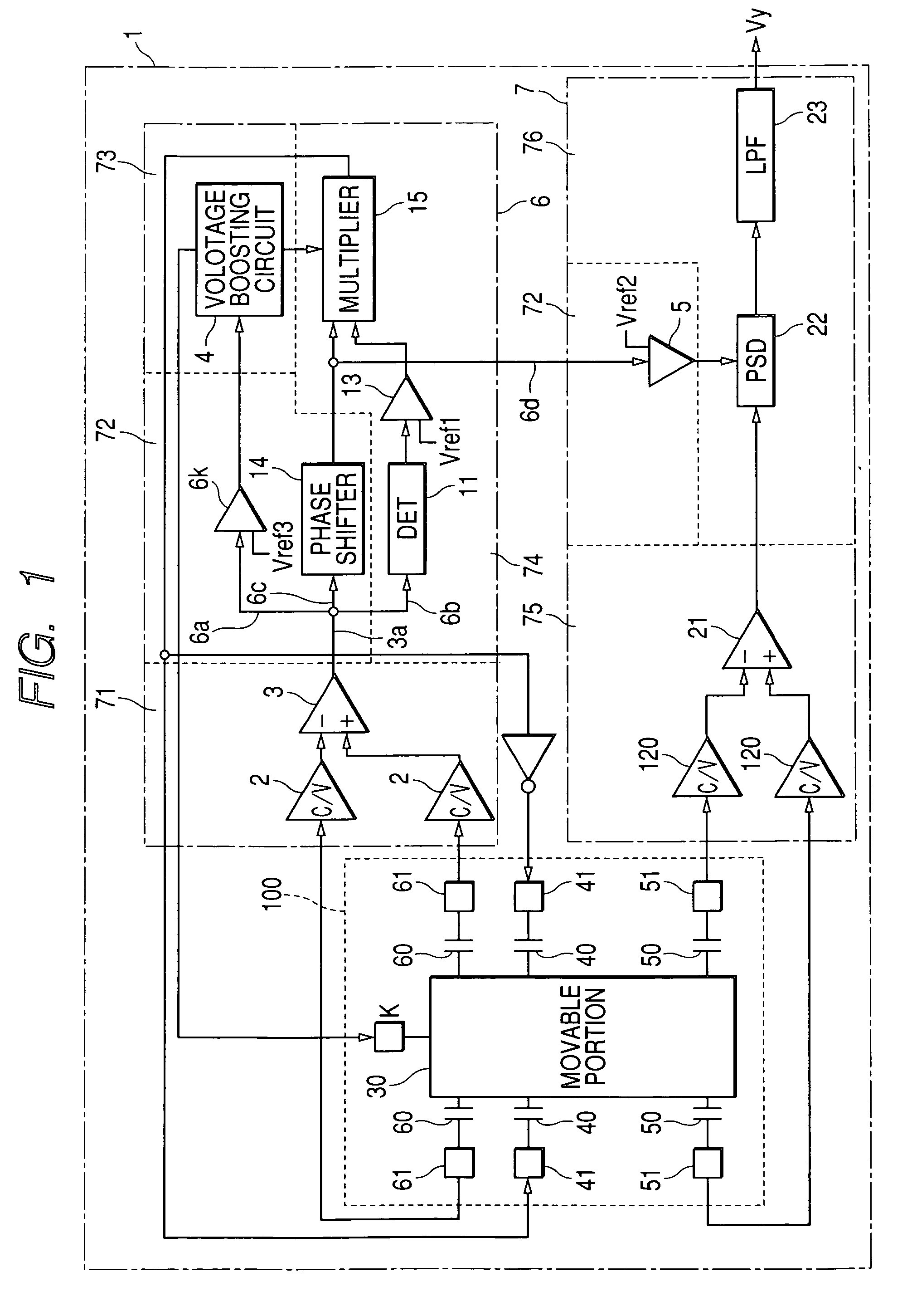
[0023]FIG. 1 is a view showing the configuration of a vibration type angular rate sensor according to an embodiment of the present invention. As shown in FIG. 1, an angular rate sensor 1 has a vibrator 100, a monitoring signal generating unit 71, a clock signal generating unit 72 and an angular velocity detecting section 7.

[0024] The vibrator 100 vibrates along a predetermined reference direction at a fixed frequency in response to a driving signal, receives an angular velocity given to the vibrator 100, and vibrates along a detecting direction perpendicular to the reference direction in accordance with the angular velocity. The generating unit 71 generates a monitoring signal which has a waveform indicating the vibration of the vibrator along the reference direction. The generating unit 72 generates, from the monitoring signal, a first clock signal and a second clock signal having a frequency identical with that of the first clock signal in a manner that a level of the first clock...


PUM


Abstract

An angular rate sensor has a vibrator vibrating along a reference direction at a fixed frequency in response to a driving signal, and vibrating along a detecting direction perpendicular to the reference direction in accordance with an angular velocity given to the vibrator. A monitoring signal generator generates a monitoring signal having a waveform of the vibrator vibration along the reference direction. A clock signal generator generates, from the monitoring signal, a first clock signal and a second clock signal having a frequency identical with that of the first clock signal and a level change occurring at a time differing from that in the second clock signal. The first clock signal is used to maintain the vibrator vibration along the reference direction. An angular velocity detector detects the angular velocity from a waveform of the vibrator vibration along the detecting direction by using the second clock signal.

Description

CROSS-REFERENCE TO RELATED APPLICATION [0001] This application is based upon and claims the benefit of priority of the prior Japanese Patent Application 2004-174688 filed on Jun. 11, 2004 so that the contents of which are incorporated herein by reference. BACKGROUND OF THE INVENTION [0002] 1. Field of the Invention [0003] The present invention generally relates to a vibration type angular rate sensor in which a vibrator vibrates in response to a driving signal, and an angular velocity given to the vibrator is detected as an angular rate while raising a level of the driving signal and applying a bias voltage to a movable portion of the vibration. [0004] 2. Description of Related Art [0005] As an angular rate sensor (or gyro sensor), a mechanical type sensor, an optical type sensor and a flowing fluid type sensor are well known. In the mechanical type, precession of a rotated body is used to detect an angular velocity given to the body as an angular rate. In the optical type, receptio...

Claims


Application Information

Patent Timeline
IPC IPC(8): G01C19/56G01C19/5726G01C19/5755G01P15/08
CPCG01C19/5719G01C19/5726
Inventor KUTSUNA, YUJIITO, HAJIME
Owner DENSO CORP
Why Eureka
Try Eureka