
Micro inertial measurement unit

a micro-inertial measurement and measurement unit technology, applied in the direction of fluid speed measurement, turn-sensitive devices, instruments, etc., can solve the problems of high power consumption, complex feedback control loops, and inability to directly obtain the attitude rate measurement from the platform, etc., to achieve position, velocity, attitude and heading measurement, the effect of high accuracy

Inactive Publication Date: 2003-12-30
AMERICAN GNC
View PDF3 Cites 52 Cited by
  • Summary
  • Abstract
  • Description
  • Claims
  • Application Information

AI Technical Summary

Benefits of technology

The micro IMU provides accurate angular, velocity, position, and heading measurements in dynamic environments, with features like miniaturization, low power dissipation, shock resistance, and high reliability, suitable for various applications including navigation systems, aircraft avionics, and spaceborne systems.

Problems solved by technology

But attitude rate measurements can not be directly obtained from the platform.
Because conventional gyros and accelerometers have a large size, high power consumption, and moving mass, complex feedback control loops are required to obtain stable motion measurements.
These present deficiencies of conventional IMUs prohibit them from use in the emerging commercial applications, such as phased array antennas for mobile communications, automotive navigation, and handheld equipment.
MEMS (MicroElectronicMechanicalSystem) inertial sensors offer tremendous cost, size, and reliability improvements for guidance, navigation, and control systems, compared with conventional inertial sensors.
Although the MEMS angular rate sensors and MEMS accelerometers are available commercially and have achieved micro chip-size and low power consumption, however, there is not yet available high performance, small size, and low power consumption IMUs.

Method used


Image

  • Micro inertial measurement unit
  • Micro inertial measurement unit
  • Micro inertial measurement unit

Examples


Embodiment Construction

Currently, MEMS exploits the existing microelectronics infrastructure to create complex machines with micron feature sizes. These machines can have many functions, including sensing, communication, and actuation. Extensive applications for these devices exist in a wide variety of commercial systems.

The difficulties for building a micro IMU is the achievement of the following hallmark using existing low cost and low accuracy angular rate sensors and accelerometers:

Low cost,

Micro size

Lightweight

Low power consumption

No wear / extended lifetime

Instant turn-on

Large dynamic range

High sensitivity

High stability

High accuracy

To achieve the high degree of performance mentioned above, a number of problems need to be addressed:

(1) Micro-size angular rate sensors and accelerometers need to be obtained. Currently, the best candidate angular rate sensor and accelerometer to meet the micro size are MEMS angular rate sensors and MEMS accelerometers.

(2) Associated mechanical structures need to be design...


PUM


Abstract

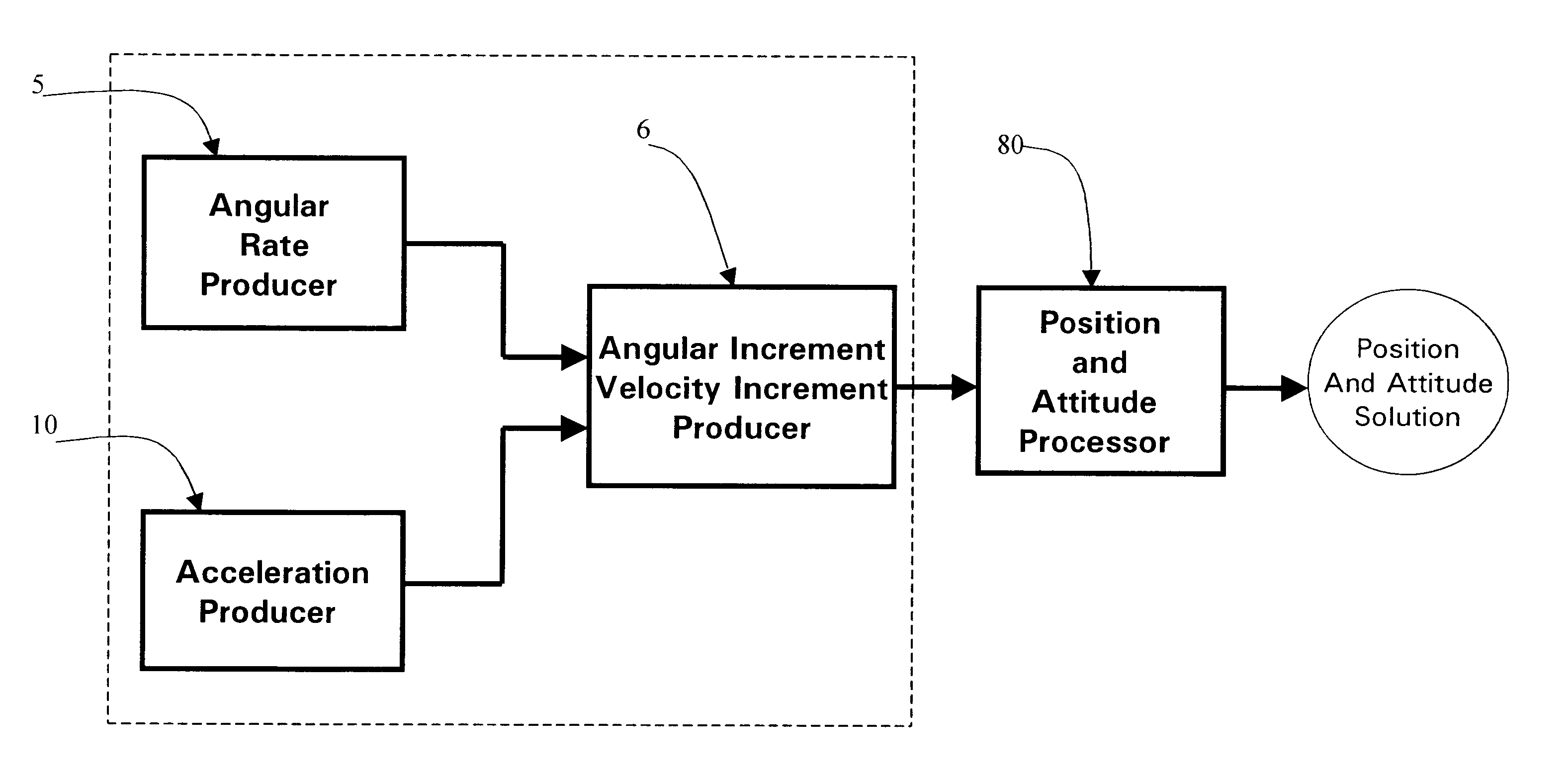
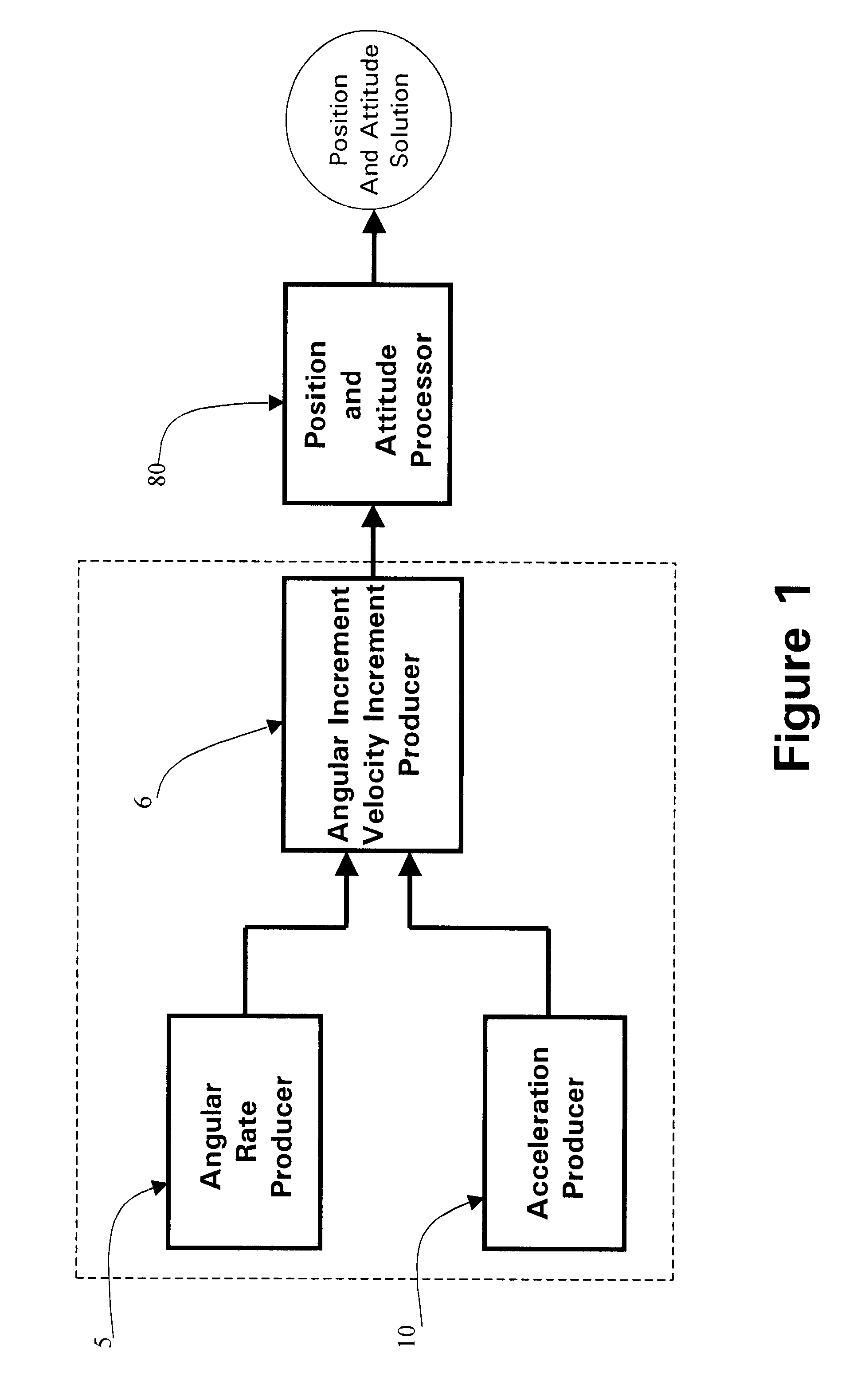
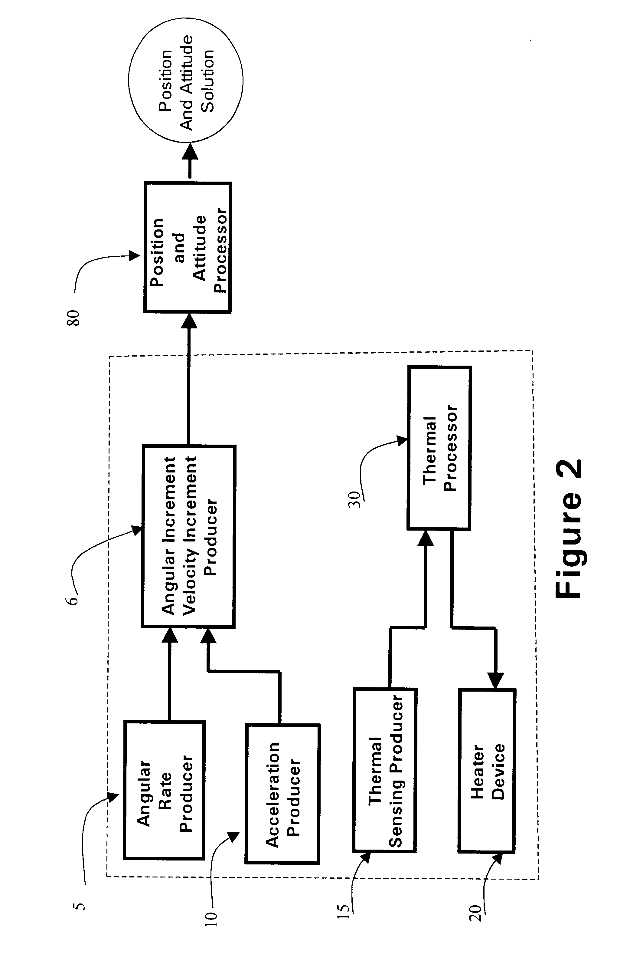
A micro inertial measurement unit, which is adapted to apply to output signals proportional to rotation and translational motion of a carrier, respectively from angular rate sensors and acceleration sensors, is employed with MEMS rate and acceleration sensors. Compared with a conventional IMU, the processing method utilizes a feedforward open-loop signal processing scheme to obtain highly accurate motion measurements by means of signal digitizing, temperature control and compensation, sensor error and misalignment calibrations, attitude updating, and damping control loops, and dramatically shrinks the size of mechanical and electronic hardware and power consumption, meanwhile, obtains highly accurate motion measurements.

Description

BACKGROUND OF THE PRESENT INVENTION1. Field of the Present InventionThe present invention relates to motion measurement, and more particularly to a motion inertial measurement unit in micro size that can produce highly accurate, digital angular increments, velocity increments, position, velocity, attitude, and heading measurements of a carrier under dynamic environments.2. Description of Related ArtsGenerally, an inertial measurement unit (IMU) is employed to determine the motion of a carrier. In principle, an inertial measurement unit relies on three orthogonally mounted inertial angular rate producers and three orthogonally mounted acceleration producers to obtain three-axis angular rate and acceleration measurement signals. The three orthogonally mounted inertial angular rate producers and three orthogonally mounted acceleration producers with additional supporting mechanical structure and electronic devices are conventionally called an Inertial Measurement Unit (IMU). The conven...

Claims


Application Information

Patent Timeline
Patent Type & Authority Patents(United States)
IPC IPC(8): G01C19/56G01C19/5719
CPCG01C19/5719
Inventor MCCALL, HIRAMLIN, CHING-FANG
Owner AMERICAN GNC
Learn More