
Apparatus and method for measuring soil gases

a technology of soil gas and apparatus, applied in the field of apparatus and methods for measuring soil gas, can solve the problems of methods not being able to make measurements without disturbing the soil air profile, many researchers defer to empirically-derived approximations, and many soils with poor diffusivity models. to achieve the effect of facilitating repeated and continuous soil gas concentration measurements

Active Publication Date: 2009-04-21
EOSENSE INC
View PDF18 Cites 21 Cited by
  • Summary
  • Abstract
  • Description
  • Claims
  • Application Information

AI Technical Summary

Benefits of technology

"The present invention provides a probe for sampling soil gas in situ, which can be easily inserted into soil to measure the gas concentration there. The probe has a waterproof membrane covering a cavity, with an inlet and an outlet for a carrier gas to introduce and exhaust the gas. The membrane is permeable to the soil gas, allowing it to diffuse into the cavity and combine with the carrier gas. The invention also includes a system for measuring soil gas concentrations using a closed-loop circuit with a carrier gas and a gas sensor. The method is minimally invasive, allowing for repeated and continuous measurements over long periods of time without altering the soil environment. The invention also provides a practical and field-portable method for measuring the diffusion coefficient of gases in soil, which is important in many types of environmental inquiry."

Problems solved by technology

The large-scale eddy covariance towers that are in operation at many key research sites are not able to resolve CO2 dynamics at the soil level and therefore surface based CO2 measurements are required.
However, many researchers defer to empirically-derived approximations such as the Millington model or improved models requiring soil-specific input parameters.
Unfortunately, diffusivity models tend to perform less well in some soils than in others.
However, these methods can not make measurements without disturbing the soil air profile.

Method used


Image

  • Apparatus and method for measuring soil gases
  • Apparatus and method for measuring soil gases
  • Apparatus and method for measuring soil gases

Examples


Embodiment Construction

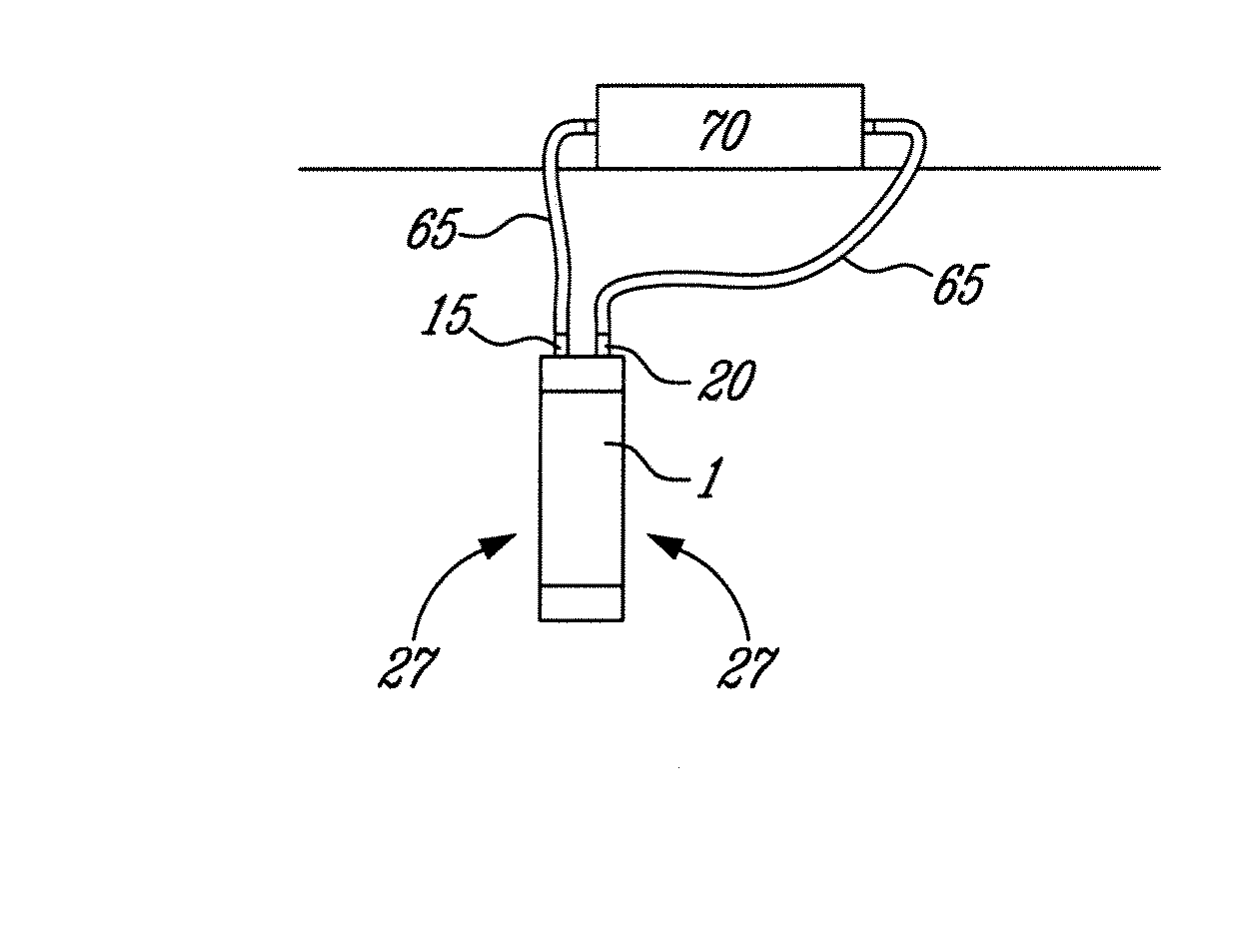
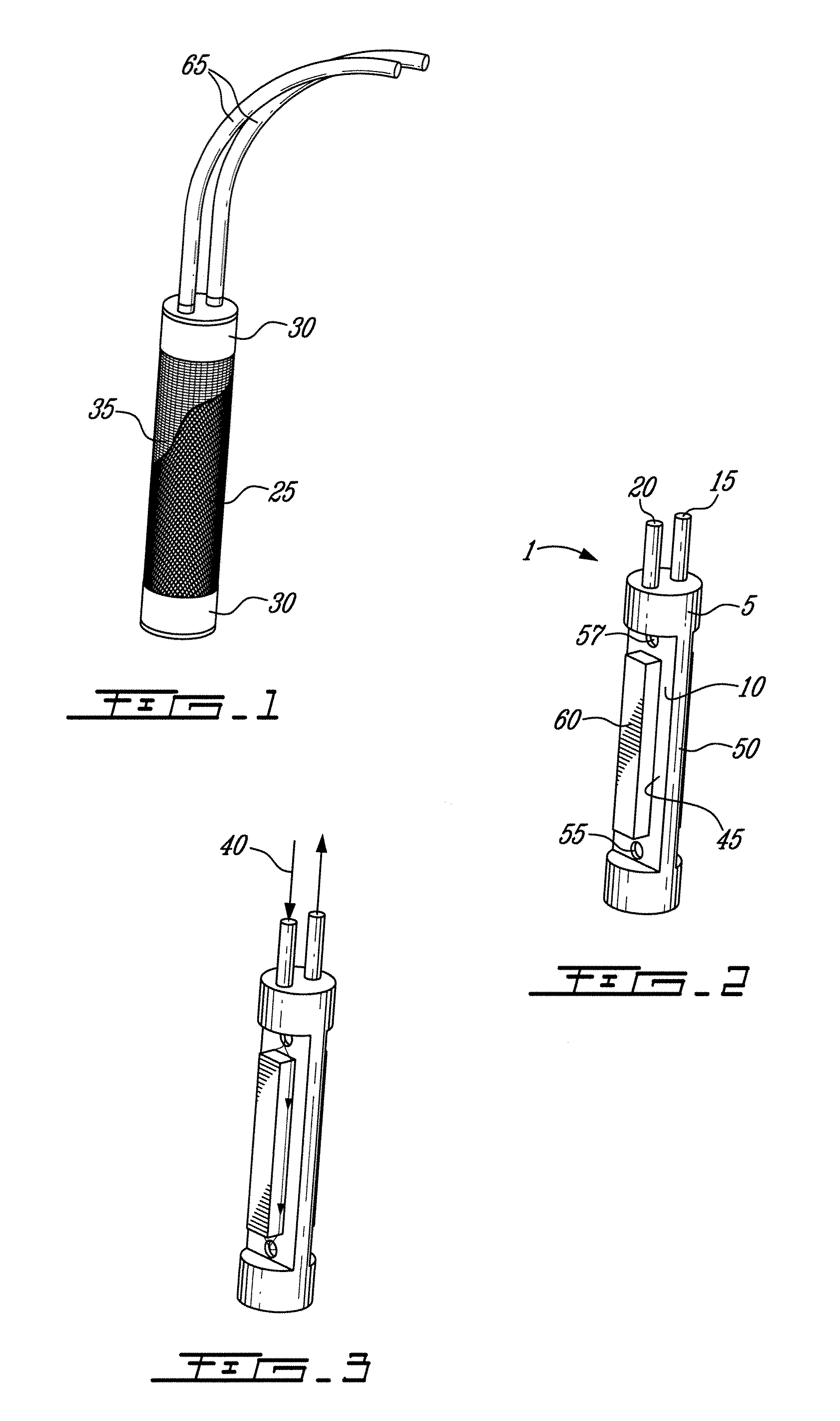
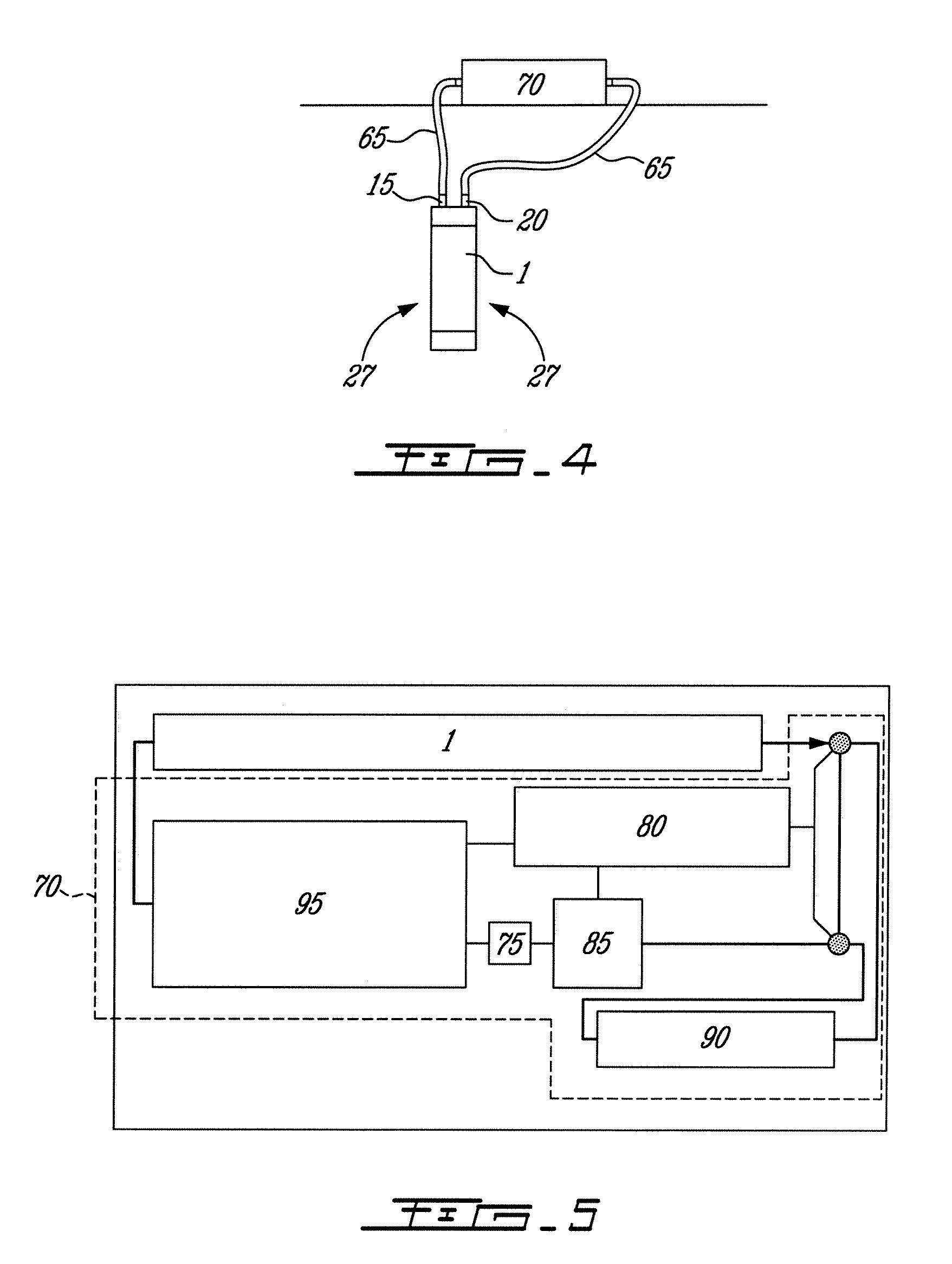
[0025]FIGS. 1 to 3 show a probe 1 intended to be buried more or less permanently in a soil gas measurement site. The probe comprises a body 5 having a cavity 10. Connected to the cavity 10 are an inlet 15 and an outlet 20. FIG. 2 shows a waterproof, microporous gas permeable membrane 25 wrapped around the body 5 and sealed with sealing means such as a sealing tape 30, for example. The membrane 25 seals the cavity 10 such that in use, soil gases 27 have to diffuse through the membrane 25 into the cavity 10. The membrane 25 may be bonded to the body 5. The cavity 10 contains a volume of air protected by the membrane 25 whose specific characteristics are selected to suit the application, in particular the required water column waterproofness, while maximizing diffusive potential.

[0026]The body 5 itself may be manufactured from metal or plastic. The membrane is covered with a tight-fitting fine stainless steel mesh 35 (partially shown) to help retain the shape of the membrane 25 against...


PUM

PropertyMeasurementUnit
permeableaaaaaaaaaa
concentrationaaaaaaaaaa
pressureaaaaaaaaaa

Abstract

A probe for sampling a soil gas comprising a body having a cavity to which is connected an inlet and an outlet, and a gas permeable waterproof membrane wrapped around the body and sealing the cavity. The membrane allows the soil gas to flow across the membrane from the soil to the cavity. A method for measuring soil gas diffusivity comprising the step of circulating in a closed loop a carrier gas substantially at an atmospheric pressure through a diffusion gas sampling probe inserted in the soil and through a sensor used for the measurement of a concentration of at least a component of the soil gas.

Description

FIELD OF THE INVENTION[0001]The present invention relates generally to soil gas measurement. More specifically, the invention relates to a new probe, system and method for measuring concentrations and diffusivity of soil gases.BACKGROUND OF THE INVENTION[0002]In temperate forests, soil respiration accounts for approximately half of total forest respiration and is regarded as the least well understood component of landscape carbon balance. Many research efforts have been aimed at determining the physical controls on total soil respiration and to that end, a wide variety of methods have been employed. The large-scale eddy covariance towers that are in operation at many key research sites are not able to resolve CO2 dynamics at the soil level and therefore surface based CO2 measurements are required. Subsurface approaches to soil CO2 monitoring are becoming increasingly popular. While requiring substantially more equipment than surface flux measurements, and limited in terms of spatial...

Claims


Application Information

Patent Timeline
Patent Type & Authority Patents(United States)
IPC IPC(8): G01N1/10
CPCG01N1/22G01N33/24G01N1/2294G01N2001/2285G01N2001/4016
Inventor RISK, DAVID A.
Owner EOSENSE INC
Learn More