Swirl generator for a radial compressor

a radial compressor and generator technology, applied in the direction of machines/engines, stators, liquid fuel engines, etc., can solve the problems of severely limited construction space available in present-day vehicle development, adverse effects on compressor output, etc., to improve construction space, enhance driving joy, and reduce emissions

Inactive Publication Date: 2009-04-21
FORD GLOBAL TECH LLC
View PDF8 Cites 2 Cited by
  • Summary
  • Abstract
  • Description
  • Claims
  • Application Information

AI Technical Summary

Benefits of technology

[0002]Radial compressors are used, for example, as turbochargers in motor vehicle engines. The construction space which is available in present-day vehicle development is severely limited due to the ever increasing number of additional assemblies and further restrictions arising from pedestrian protection or crash safety requirements. The result is that engine components, lines and air-carrying pipes compete with other components and structural parts for the respectively ideal location. In modern engine construction, the additional assemblies also include exhaust-gas turbochargers, which serve to boost the specific power output and torque in order to enhance the joy of driving and, at the same time, offer prospects for reduced emissions. Associated with turbochargers and boost concepts are other components, such as, for example, charge-air coolers, control valves and additional air pipe installations, which additionally aggravate the construction space situation.
[0011]According to the present invention, a compact configuration of the swirl generator with bends and integrated pre-swirl generation is provided, the configuration of the swirl generator giving due consideration to the limited construction space conditions within the engine compartment by taking up relatively little construction space. In addition, an enveloping compressor characteristic diagram of all swirl settings is widened, the surge limit of the compressor being shifted by the swirl to smaller mass flows. Therefore, the drivability of motor vehicles, with regard to torques in the lower region of the vehicle engine, the rated power of the engine and the acceleration characteristics, is significantly improved.

Problems solved by technology

The construction space which is available in present-day vehicle development is severely limited due to the ever increasing number of additional assemblies and further restrictions arising from pedestrian protection or crash safety requirements.
This can lead to irregularities in the approach flow and to local flow separations, especially at the compressor wheel, in which case the compressor output is adversely affected by the non-uniformity.

Method used


Image

  • Swirl generator for a radial compressor
  • Swirl generator for a radial compressor
  • Swirl generator for a radial compressor

Examples


Embodiment Construction

)

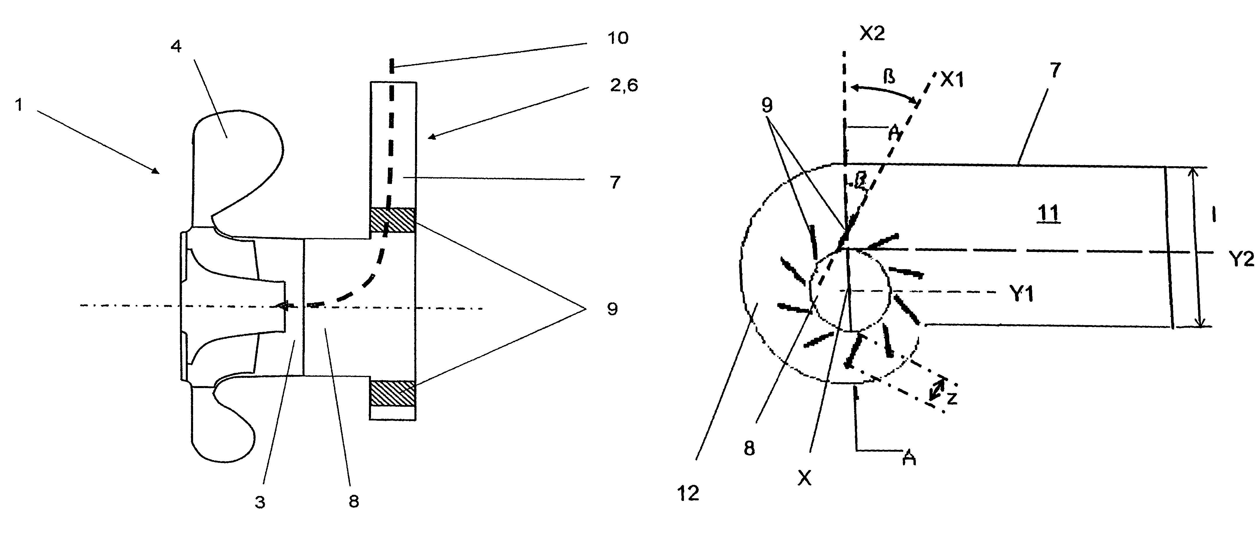
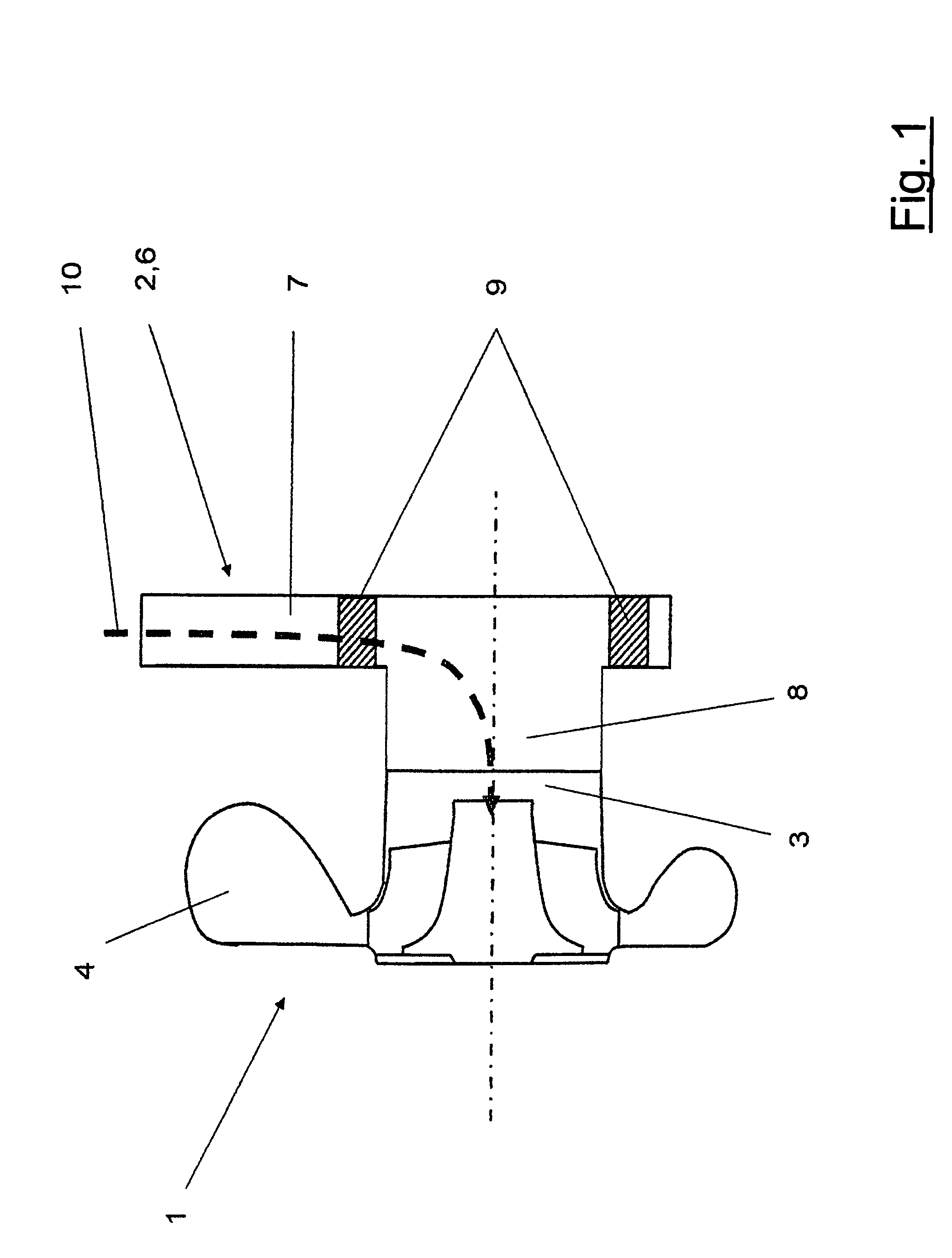
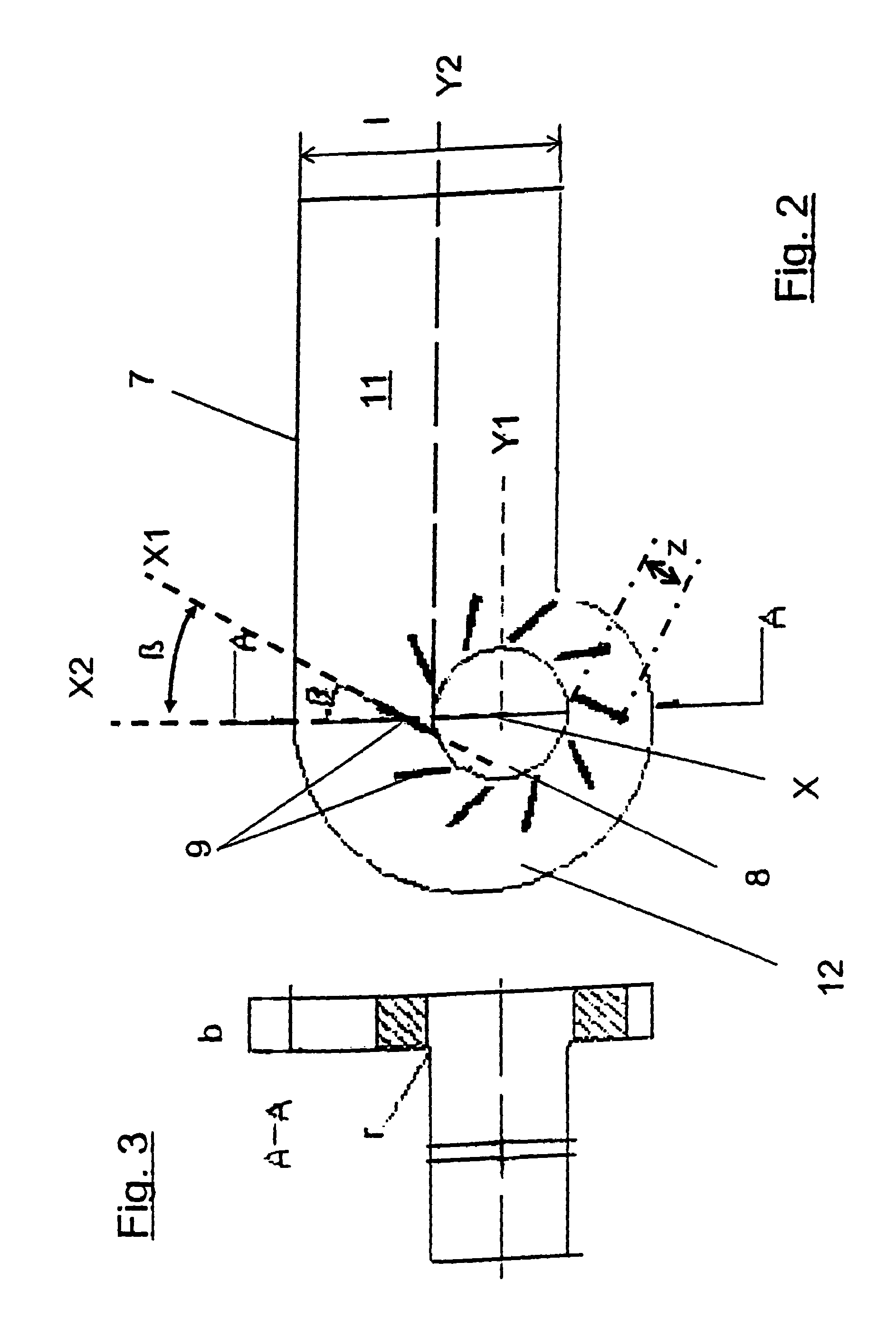
[0020]FIG. 1 shows a radial compressor 1 having an upstream swirl generator 2. The radial compressor 1 has a suction-side opening 3 and a pressure side 4. The suction-side opening 3 is assigned an approach flow line 6, which has an inlet portion 7 and at least one outlet opening 8, which latter emerges in the suction-side opening 3. The approach flow line 6 is configured as a swirl generator 2. The swirl generator 2, with its inlet portion 7, is angularly configured relative to the outlet opening 8, the swirl generator 2 having adjustable baffle plates 9, which are arranged concentrically around the outlet opening 8 (described in more detail in FIG. 2 below). In a preferred embodiment, the inlet portion 7 is arranged at a right angle to the outlet opening 8, so that a 90° flow deflection of a flow medium is obtained. The flow deflection is represented in FIG. 1, by way of example, as the flow arrow 10. Of course, the inlet portion 7 can be arranged at any sensible angle, preferably...


PUM


Abstract

The invention relates to a radial compressor having a suction-side opening and a pressure side. A swirl generator is placed upstream of the radial compressor. The swirl generator, has an inlet portion which is angularly configured relative to the outlet opening, the outlet opening facing the suction-side opening of the swirl generator. The swirl generator further has adjustable baffle plates arranged concentrically around the outlet opening.

Description

FIELD OF INVENTION[0001]The invention relates to a turbocharger for an internal combustion engine, and in particular to a radial compressor with an improved swirl generator.BACKGROUND AND SUMMARY OF THE INVENTION[0002]Radial compressors are used, for example, as turbochargers in motor vehicle engines. The construction space which is available in present-day vehicle development is severely limited due to the ever increasing number of additional assemblies and further restrictions arising from pedestrian protection or crash safety requirements. The result is that engine components, lines and air-carrying pipes compete with other components and structural parts for the respectively ideal location. In modern engine construction, the additional assemblies also include exhaust-gas turbochargers, which serve to boost the specific power output and torque in order to enhance the joy of driving and, at the same time, offer prospects for reduced emissions. Associated with turbochargers and boo...

Claims


Application Information

Patent Timeline
Patent Type & Authority Patents(United States)
IPC IPC(8): F04D29/46F04D27/02F04D29/42F04D29/44
CPCF04D27/0246F04D29/4213F04D29/441F04D29/462F05D2250/51
Inventor KINDL, HELMUT M.SCHORN, NORBERT A.SPAEDER, UWE R.STALMAN, ROB
Owner FORD GLOBAL TECH LLC
Why Eureka
Try Eureka