Multi-Channel signal acquisition probe

a signal acquisition and multi-channel technology, applied in the field of multi-channel signal acquisition probes, can solve the problems of multiple discontinuities in the signal path, inconvenient installation, and high construction costs of multi-channel general purpose probes available today, and achieve the effects of easy installation, easy installation and maintenance, and high construction efficiency

Inactive Publication Date: 2009-04-21
TEKTRONIX INC
View PDF15 Cites 38 Cited by
  • Summary
  • Abstract
  • Description
  • Claims
  • Application Information

AI Technical Summary

Problems solved by technology

Most high performance multi-channel general purpose probes available today have inherent construction expenses and related performance issues.
A disadvantage of the above design is that there are multiple discontinuities in the signal path due to the soldering of the coaxial signal cables of the ribbon cable and the individual coaxial signal cables to the midpoint board and the soldering of the coaxial signal cable and the ribbon cable to connections at the ends of the cables.
Coaxial cables are difficult and labor intensive to attach to a board because there are inner and outer conductors with insulating material in between that need to prepared and connected without shorting the inner and outer conductors together.
Attaching ribbonized coaxial signal cables to the board is even more complex and expensive.
However, this design has the disadvantage of longer individual coaxial cables that are difficult to manage and keep from being tangled, caught or damaged in normal use.
However, the sleeve represents extra material and labor expense that diminishes the savings in the electrical assembly.
This approach also has the disadvantage in that there is no place to connect a signal ground common to all of the channels unless it is all the way back at the connection with the measurement test instrument which is relatively far from the device under test.
Further, the probe holder with the electrically conductive ground clip only works when the probes are ganged together in the holder.
For applications where the probes are distributed on probing points across the device under test, this solution does not work.

Method used


Image

  • Multi-Channel signal acquisition probe
  • Multi-Channel signal acquisition probe
  • Multi-Channel signal acquisition probe

Examples


Embodiment Construction

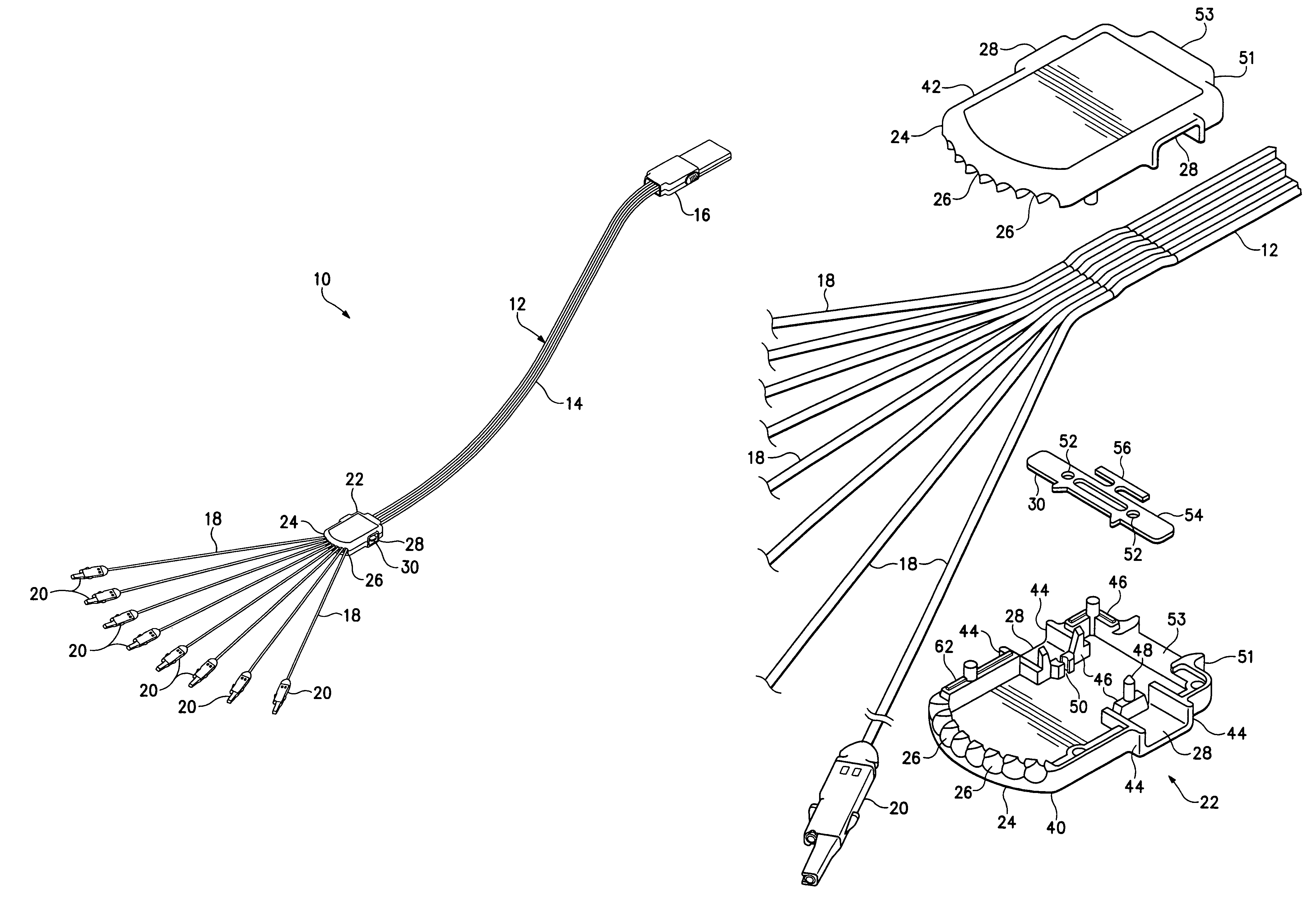
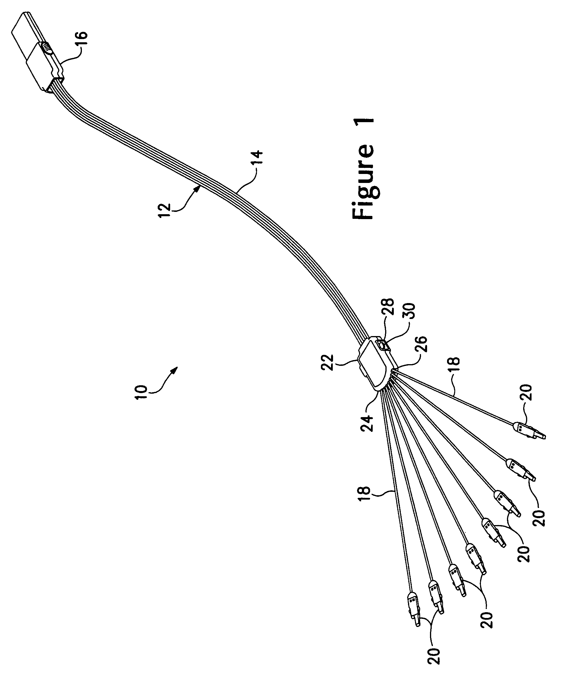
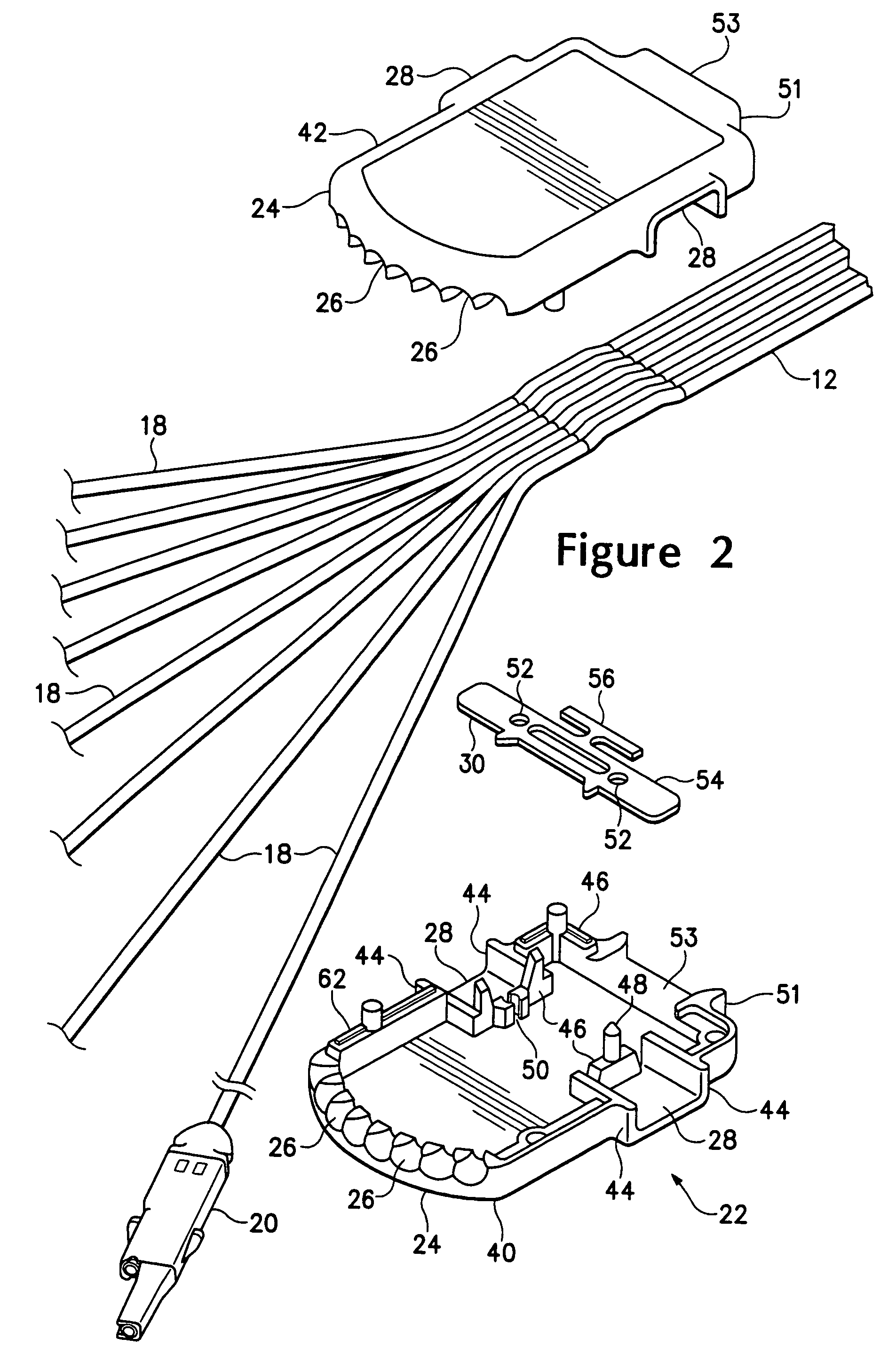
[0024]Referring to FIG. 1, there is shown a perspective view of the multi-channel signal acquisition probe 10. The multi-channel signal acquisition probe 10 has a ribbon cable 12 having ganged coaxial signal cables 14. One end of the ribbon cable 12 is connected to a terminal connector 16 for connecting the multi-channel signal acquisition probe 10 to a measurement test instrument, such as a mixed signal oscilloscope, logic analyzer or the like (not shown). The coaxial signal cables 14 at the other end of the ribbon cable 12 are separated into individual coaxial signal cables 18. Each of the individual coaxial signal cables 18 has a probing head 20 for connecting to a device under test (not shown). A junction box 22 is mounted on the ribbon cable 12 where the ganged coaxial signal cables 14 are separated into the individual coaxial signal cables 18. The junction box 22 has a front face 24 with apertures 26 therein from which extend the individual coaxial signal cables 18. Openings 2...


PUM

PropertyMeasurementUnit
electrically conductiveaaaaaaaaaa
distanceaaaaaaaaaa
lengthaaaaaaaaaa

Abstract

A multi-channel signal acquisition probe has a ribbon cable with ganged coaxial signal cables. The coaxial signal cables are separated into individual cables at one end of the ribbon cable. A junction box is mounted the ribbon cable with the individual cables extending through apertures in a front face of the junction box. An electrically conductive terminal is disposed in the junction box and extends into openings in opposing sides of the junction box. The electrically conductive terminal is electrically coupled to each outer shielding conductor of the signal cables. The free ends of each of the individual signal cables has a probing head. A terminal connector is disposed on the other end of the ribbon cable.

Description

BACKGROUND OF THE INVENTION[0001]The present invention related generally to signal acquisition probes and more particularly to a multi-channel signal acquisition probe usable for acquiring logic signal from a device under test.[0002]Multi-channel signal acquisition probes are generally used to acquire multiple signals from a device under test. A multi-channel general purpose probe has a single connector one end that couples to a measurement test instrument, such as a logic analyzer, mixed signal oscilloscope or the like. The other end of the multi-channel general purpose probe has individual cables with electrical connectors disposed in housings at the ends of the cables for connecting to separate location on the device under test. High performance multi-channel general purpose probes have a controlled electrical environment the length of the probe that is generally achieved using coaxial signal cables.[0003]Most high performance multi-channel general purpose probes available today ...

Claims


Application Information

Patent Timeline
Patent Type & Authority Patents(United States)
IPC IPC(8): H01B7/00
CPCG01R1/06788G01R31/3177G01R1/06766G01R1/073
Inventor CLEM, JONATHAN D.MEYER, DANIEL B.
Owner TEKTRONIX INC
Why Eureka
Try Eureka