
Dimmer circuit for a discharge lighting apparatus

a lighting apparatus and discharge lamp technology, applied in lighting and heating apparatus, process and machine control, instruments, etc., can solve the problems of difficult to maintain a stable discharge and easy out of discharge lamps

Inactive Publication Date: 2009-04-21
MINEBEA CO LTD
View PDF15 Cites 0 Cited by
  • Summary
  • Abstract
  • Description
  • Claims
  • Application Information

AI Technical Summary

Benefits of technology

The present invention is a discharge lamp lighting apparatus with a dimmer circuit that can adjust the brightness of the screen based on an input signal or user operation. The dimmer circuit includes an amplitude adjusting circuit, an integration circuit, and a comparison circuit that generates a dimming signal to perform a burst dimming mode of the discharge lamp. This allows for a dimming operation over a wide range without creating a brightness gradient between the high and low tension sides of the lamp. Additionally, the dimmer circuit can use an external digital-analog converting circuit or an external analog signal to generate the first and second dimming control signals. Overall, the discharge lamp lighting apparatus with the dimmer circuit provides dynamic control over screen brightness and improved cold start performance.

Problems solved by technology

Also, if a lamp current is reduced below the guarantee value of the discharge lamp, the discharge lamp exhibits an unstable discharge operation, which causes a problem of flickering, and also causes difficulty of maintaining a stable discharge operation therefore allowing the discharge lamp to readily go out.

Method used


Image

  • Dimmer circuit for a discharge lighting apparatus
  • Dimmer circuit for a discharge lighting apparatus
  • Dimmer circuit for a discharge lighting apparatus

Examples


Embodiment Construction

[0028]An exemplary embodiment of the present invention will be described with reference to the accompanying drawings.

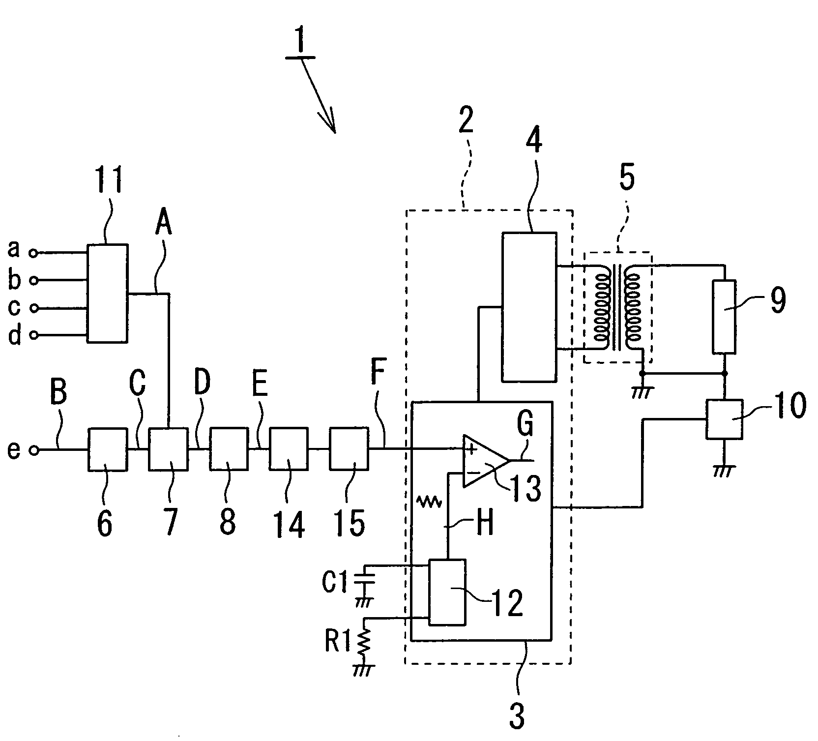
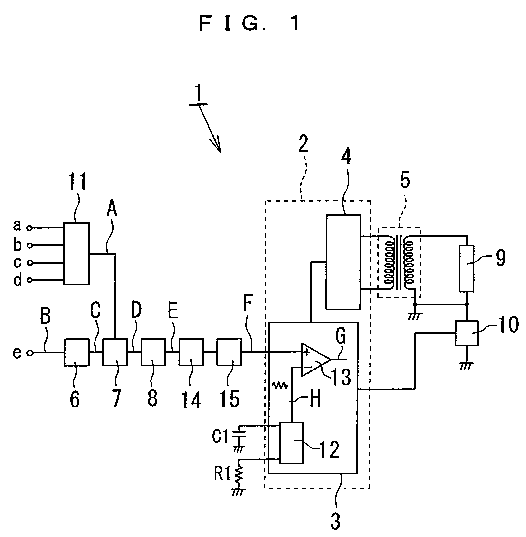
[0029]Referring to FIG. 1, a discharge lamp lighting apparatus 1 according to an embodiment of the present invention includes an inverter circuit 2, and a step-up transformer 5. The inverter circuit 2 includes a switch circuit 4 to drive the primary side of the step-up transformer 5, and a control circuit 3 to control the operation of the switch circuit 4. A discharge lamp 9, such as a cold cathode tube, is connected at the secondary side of the step-up transformer 5, and one terminal of the discharge lamp 9 is grounded via a lamp current detecting circuit 10. The discharge lamp lighting apparatus 1 according to the present embodiment is adapted to control lighting of the discharge lamp 9 and is used as a backlight device for an LCD (not shown).

[0030]A dimmer circuit in the discharge lamp lighting apparatus 1 will hereinafter be described. The dimmer circuit of the di...


PUM


Abstract

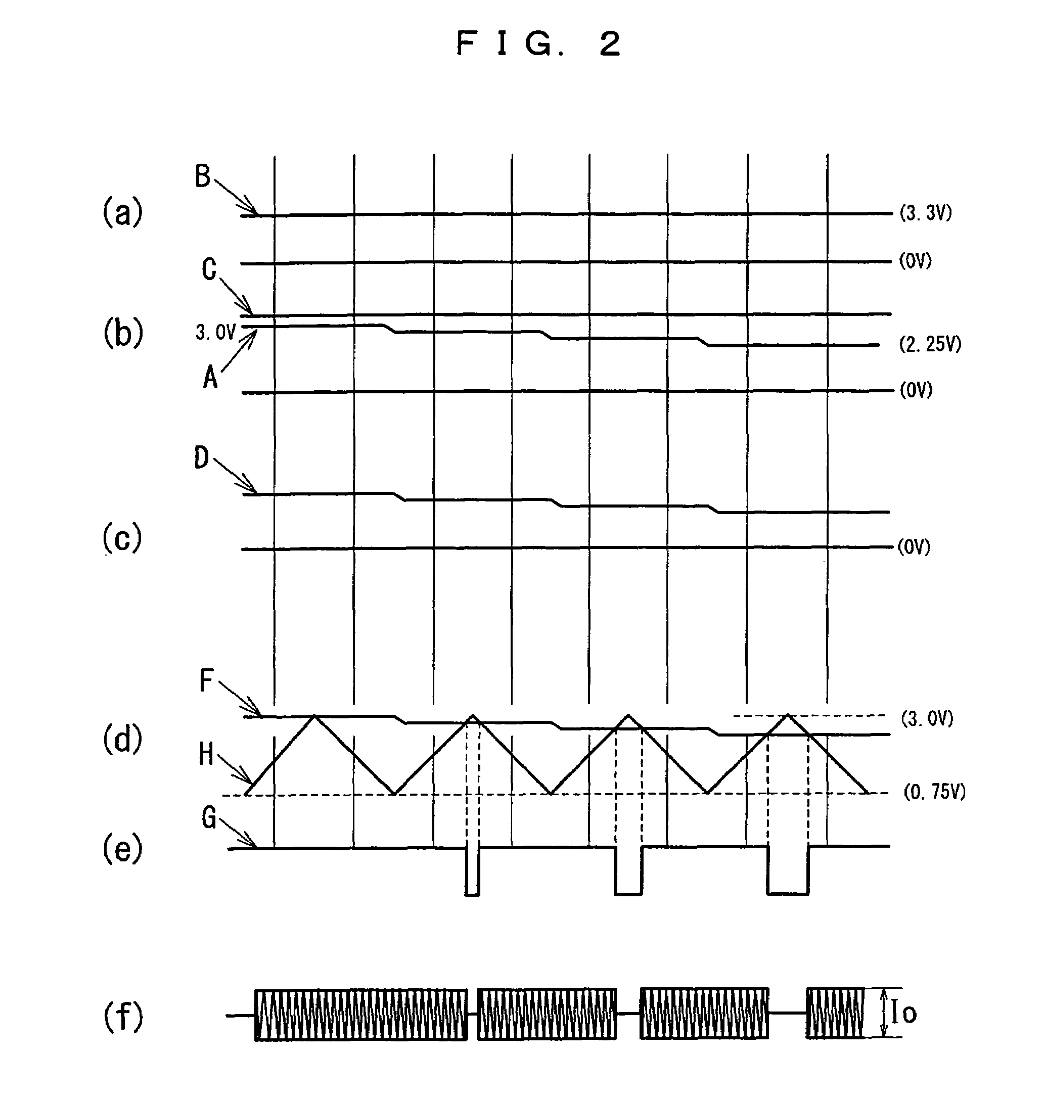
There is provided a discharge lamp lighting apparatus including a dimmer circuit which is provided with a control means to dynamically adjust screen brightness according to an input signal, and a control means to adjust screen brightness based on a user's operation. The dimmer circuit includes: an amplitude adjusting circuit to superpose a first dimming control signal composed of a DC voltage onto a second dimming control signal composed of a pulse width modulation signal; an integration circuit to integrate an output of the amplitude adjusting circuit; and a comparison circuit to compare an output of the integration circuit with a triangular wave having a predetermined frequency thereby generating a dimming signal, wherein a burst dimming mode is performed according to the dimming signal.

Description

BACKGROUND OF THE INVENTION[0001]1. Field of the Invention[0002]The present invention relates to a discharge lamp lighting apparatus to light a discharge lamp for illuminating a liquid crystal display (LCD) device, and more particularly to a discharge lamp lighting apparatus having a dimmer circuit which includes a control means to dynamically control screen brightness according to an input signal, and also a control means to control the screen brightness based on the user's operation, and which enables a dimming operation to be performed over a wide range without generating a brightness gradient even when a long lamp is used.[0003]2. Description of the Related Art[0004]A lighting apparatus such as a backlight device is employed in an LCD device used as a display device for an LCD monitor, an LCD television, and the like. A discharge lamp such as a cold cathode lamp is extensively used as a light source for such a lighting apparatus. A discharge lamp lighting apparatus is usually pr...

Claims


Application Information

Patent Timeline
Patent Type & Authority Patents(United States)
IPC IPC(8): G05F1/00
CPCH05B37/0263H05B47/185
Inventor SUZUKI, SHINICHIMATSUSHIMA, MITSUO
Owner MINEBEA CO LTD
Learn More