Ultrasonic sensor having compressively deformed spring resiliently attaching sensor body and bezel

a technology of compressively deformed springs and sensors, applied in the field of ultrasonic sensors, can solve the problem that the sensor body cannot be inserted into the hole in the bumper

Active Publication Date: 2009-04-21
DENSO CORP
View PDF14 Cites 11 Cited by
  • Summary
  • Abstract
  • Description
  • Claims
  • Application Information

AI Technical Summary

Benefits of technology

[0013]Furthermore, the flange may define a space between an outer face of the component, and the spring may protrude from the outer face into the space. In this manner, the spring may effectively contribute to the attachment of the bezel on the component.

Problems solved by technology

The sensor body is accordingly enlarged, and a problem occurs such that the sensor body cannot be inserted in the hole in the bumper from the outside of the bumper.
The above-described problem also arises when the ultrasonic sensor is attached to a part of the vehicle that is different from a bumper in a vehicle body.

Method used


Image

  • Ultrasonic sensor having compressively deformed spring resiliently attaching sensor body and bezel
  • Ultrasonic sensor having compressively deformed spring resiliently attaching sensor body and bezel
  • Ultrasonic sensor having compressively deformed spring resiliently attaching sensor body and bezel

Examples


first embodiment

[0033]An ultrasonic sensor according to a first embodiment of the invention will be described. An ultrasonic sonar of the present embodiment is attached to, for example, a bumper of a vehicle and is used as a back sonar or a corner sonar.

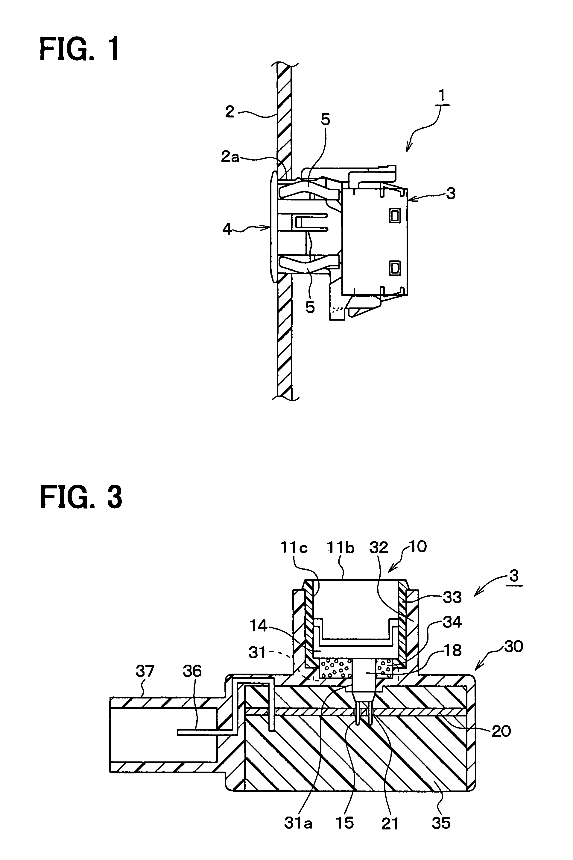
[0034]FIG. 1 is a side view showing a state in which an ultrasonic sensor 1 of the embodiment is attached to a bumper 2. In FIG. 1, only the bumper 2 is shown as a section.

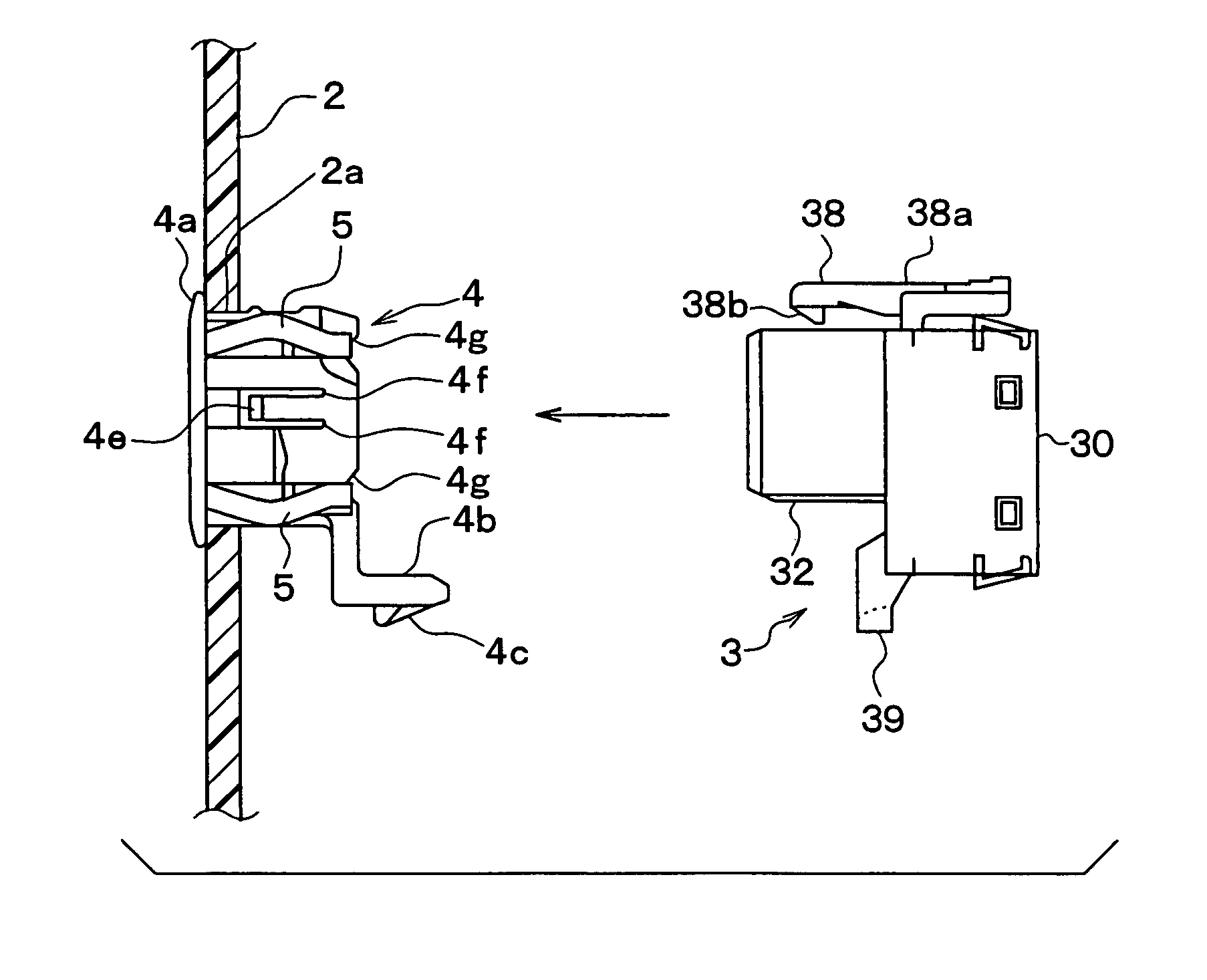
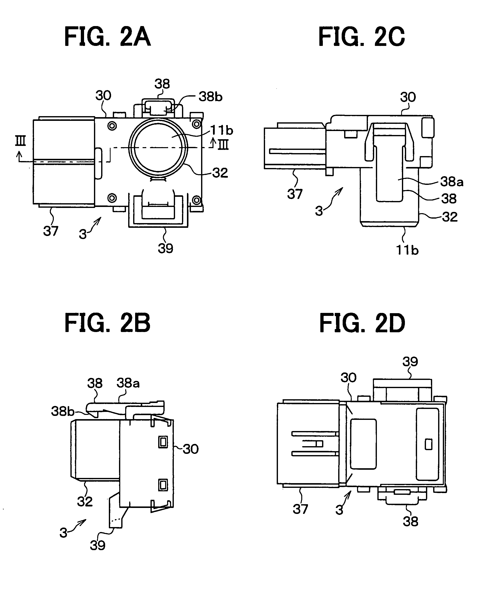
[0035]As shown in the diagram, the ultrasonic sensor 1 is fixed in a hole 2a in the bumper 2. The ultrasonic sensor1 has a configuration including the sensor body 3 and a bezel 4. The bezel 4 is inserted into the hole 2a in the bumper 2 from the outside of the bumper 2 (i.e., from the left side of the drawing) and, after that, the sensor body 3 is inserted into the hollow in the bezel 4 from the inside of the bumper 2 (i.e., from the right side of the drawing), thereby fixing the ultrasonic sensor 1 to the bumper 2.

[0036]The detailed structure of the sensor body 3 and the bezel 4 ...

second embodiment

[0073]FIGS. 10A, 10B, 10C, 10D, 10E are a front view, left-side view, rear view, top view, bottom view, respectively, of the bezel 4. FIG. 11 is a partially enlarged cross section of the bezel 4, taken along a line XI-XI of FIG. 10C.

[0074]As shown in FIGS. 10A to 10E, the bezel 4 is constructed by an almost cylindrical member made of a material such as a resin softer than a metal. A flange 4a whose diameter is partly enlarged is formed at one end of the bezel 4. The shape and size of the hollow of the bezel 4 correspond to those of the open face 32 in the sensor body 3. In the hollow, the open face 32 and the ultrasonic transducer 10 are inserted.

[0075]The flange 4a of the bezel 4 has a cross section in an arc shape, and a tip of the flange 4a has a contact with the bumper 2. More practically, a radially farthest portion of the flange 4a that extends outwardly from an axis of the cylindrical shape touches the bumper 2 on its surface. In this manner, a space between broken lines A an...


PUM


Abstract

An ultrasonic sensor has a sensor body and a bezel having a metal spring attached on a side wall thereof for installation on a vehicle component. A free end of the metal spring is positioned to protrude from a through hole of the side wall, is pressed by a portion of the sensor body that is inserted in a hollow space of the bezel, and is pushed back by an opening face of the sensor body. In this manner, the bezel is firmly attached on the component and the sensor body is firmly attached on the bezel.

Description

CROSS REFERENCE TO RELATED APPLICATION[0001]This application is based on and claims the benefit of priority of Japanese Patent Application No. 2006-71288 filed on Mar. 15, 2006, and of Japanese Patent Application No. 2006-71289 filed on Mar. 15, 2006, the disclosure of which is incorporated herein by reference.FIELD OF THE INVENTION[0002]The present invention relates to an ultrasonic sensor having an ultrasonic transducer that includes a piezoelectric element.BACKGROUND INFORMATION[0003]A conventional ultrasonic sensor has, for example, a sensor body with an ultrasonic transducer installed therein attached to the bumper of a vehicle. Ultrasonic waves are generated by the ultrasonic transducer and, by receiving reflection waves of the ultrasonic waves, an obstacle existing near the bumper is detected.[0004]FIG. 17 is a partial cross section showing a structure of fixing the conventional ultrasonic sensor 100 to a bumper 101. As shown in the diagram, a sensor body 102 of the ultrasoni...

Claims


Application Information

Patent Timeline
Patent Type & Authority Patents(United States)
IPC IPC(8): G01D11/24
CPCG01S7/521G10K9/22
Inventor NAKAJIMA, AKIRAKAWASHIMA, YASUHIROKANI, HIROYUKISHIMIZU, TADAO
Owner DENSO CORP
Why Eureka
Try Eureka