Loose tube optical waveguide fiber cable

a fiber cable and optical waveguide technology, applied in the field of loose tube optical waveguide fiber cable, can solve the problems of time-consuming access to fibers, high cost of tight buffered cables, and high cost of central-filled loose tubes, and achieve the effect of cost-effectiveness

Inactive Publication Date: 2009-04-21
DRAKA COMTEQ BV
View PDF12 Cites 15 Cited by
  • Summary
  • Abstract
  • Description
  • Claims
  • Application Information

AI Technical Summary

Benefits of technology

[0011]One of the objects of the present invention is to provide a loose tube optical waveguide fiber cable that is suitable for fixed in-house cabling and is extremely cost-effective for a large-scale installation of FTTH.

Problems solved by technology

Such tight buffered cables, however, are expensive and accessing the fibers is time-consuming.
Central-filled loose tubes are expensive, too, and require fiber cleaning.
In addition, these gel-filled central loose tubes have high minimum cable bend radii due to kinking of the loose tube.

Method used


Image

  • Loose tube optical waveguide fiber cable
  • Loose tube optical waveguide fiber cable

Examples


Embodiment Construction

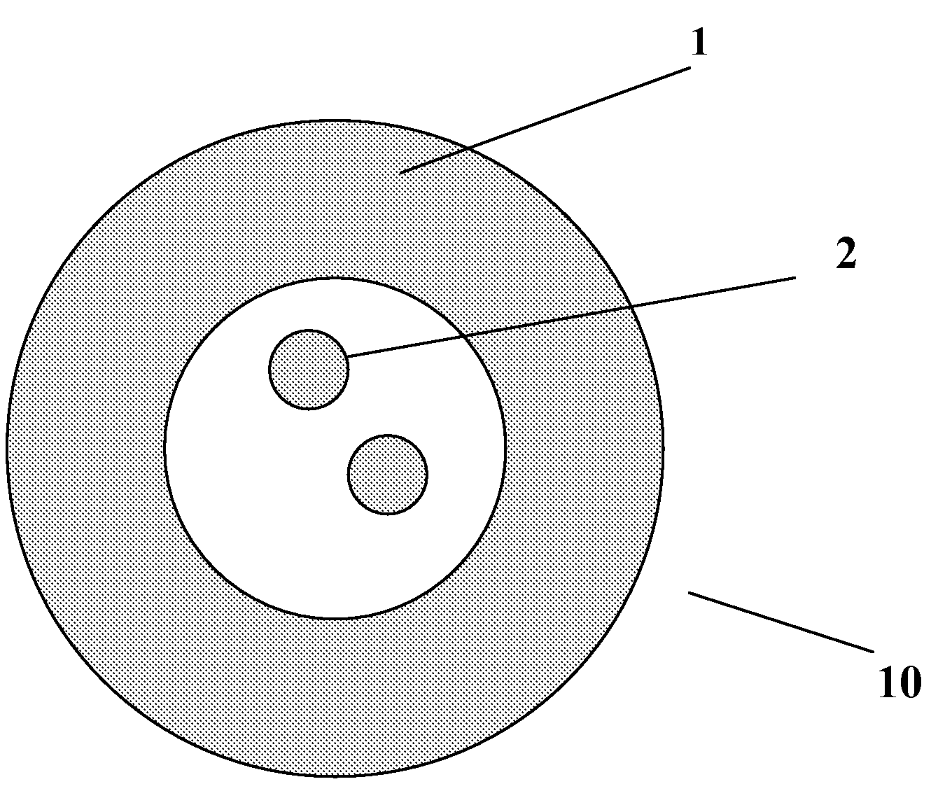
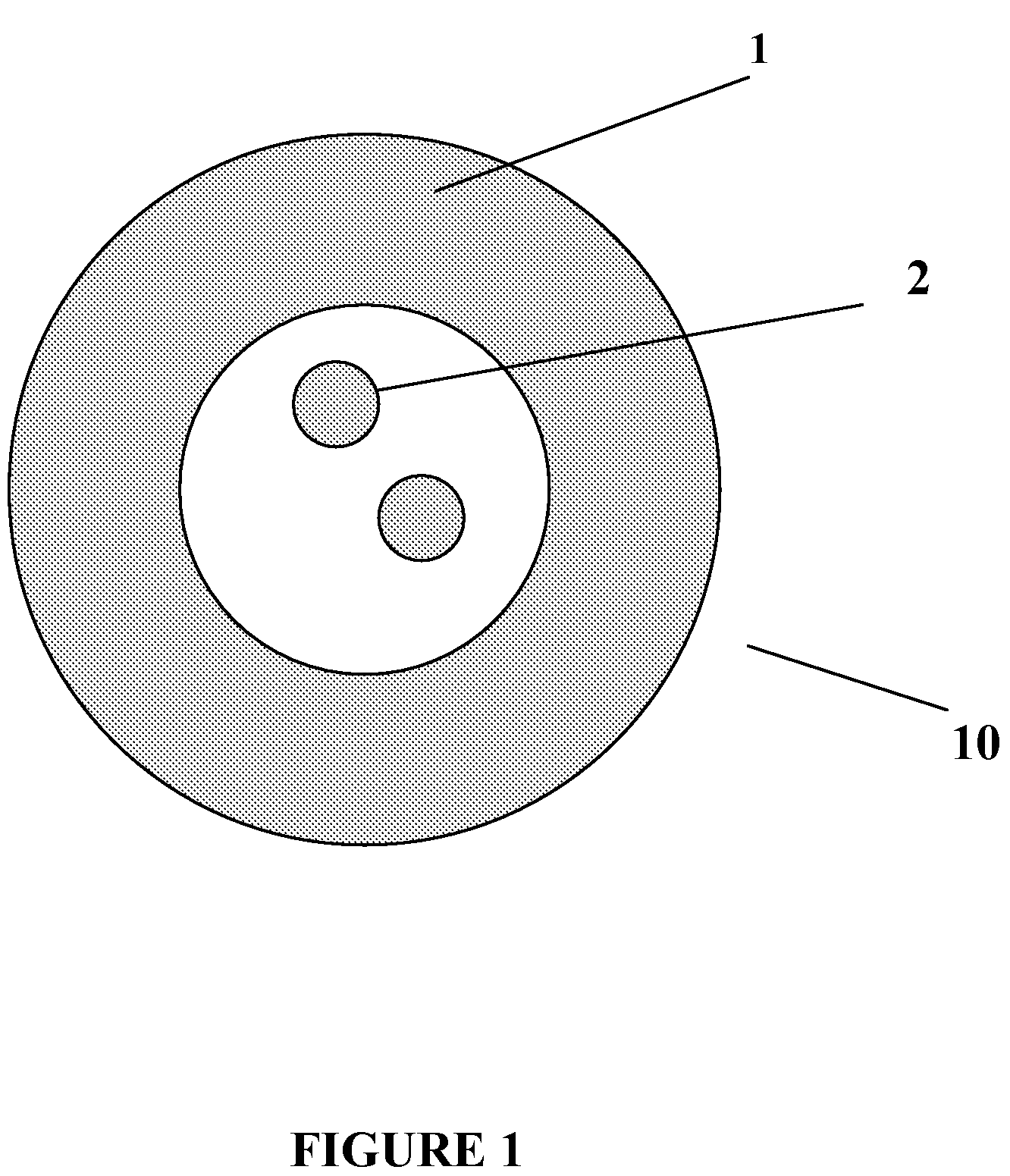
[0016]A loose tube optical waveguide fiber cable 10 according to the present invention may be constructed as schematically depicted in FIG. 1. The cable 10 contains two optical fibers 2 surrounded by a coating (not shown) that is applied directly over the optical fiber 2. The optical fiber 2 may contain a core and a cladding surrounding the core, with one or more polymer coatings applied over the cladding. The protective tube 1 (or outer jacket), which is formed of flame-retardant material, loosely surrounds the optical fibers 2. In other words, the optical fibers 2 are loosely provided within the protective tube 1. The number of optical fibers 2 is not restricted to a specific number.

[0017]The cable 10 contains neither gel-like compounds nor any strengthening members. Accordingly, protective tube 1 is a hollow structure of uniform composition and has open space between the optical fibers 2 and the inner wall of the tube 1. Cable 10 is suitable for riser or plenum applications.

[0018...


PUM


Abstract

The present invention relates to loose tube optical waveguide fiber cable which is optimized for easy and fast installation as plenum cable, such as in customer premises for FTTH (fiber to the home) applications. One of the objects of the present invention is to provide a loose tube optical waveguide fiber cable which is suitable for fixed in-house cabling at extremely low-cost for a large-scale installation of FTTH.

Description

CROSS-REFERENCE TO PRIORITY APPLICATION[0001]This application hereby claims the benefit of pending International Application No. PCT / NL2006 / 000440 (filed Aug. 31, 2006, at the Dutch Patent Office) via 35 U.S.C. §365(a). International Application No. PCT / NL2006 / 00040 is hereby incorporated by reference in its entirety.FIELD OF THE INVENTION[0002]The present invention relates to a loose tube optical waveguide fiber cable that is optimized for easy and fast installation as plenum cable, such as in customer premises for FTTH (fiber to the home) applications.BACKGROUND OF THE INVENTION[0003]Optical waveguide fibers are normally provided with a plastic protective coating applied by the fiber manufacturer directly over the cladding in order to protect the fiber.[0004]In tight buffered cables, a protective tube is applied by the cable manufacturer directly to the outer surface of the protective fiber coating so that the fiber and the tube are in contact substantially along their length. Suc...

Claims


Application Information

Patent Timeline
Patent Type & Authority Patents(United States)
IPC IPC(8): G02B6/44
CPCG02B6/4436
Inventor NOTHOFER, KLAUSLAUSCH, PETER
Owner DRAKA COMTEQ BV
Why Eureka
Try Eureka