Automatic generation of component interfaces for computational hardware implementations generated from a block diagram model

Active Publication Date: 2009-04-21
THE MATHWORKS INC
View PDF3 Cites 43 Cited by
  • Summary
  • Abstract
  • Description
  • Claims
  • Application Information

AI Technical Summary

Benefits of technology

[0008]The present invention provides systems and methods to represent in a graphical model an interface between electronic components of a target computational hardware device and to automatically generate code from the graphical model to implement the component interface on the target device. A graphical modeling environment provides for a graphical model design that can be targeted for implementation on one or more computational hardware de

Problems solved by technology

In these types of cases, it is much more challenging and difficult to generate an implementation, such as generating code, from a model-based design as the implementation is dependent on the topology of the hardware.
Moreover, with the wide range of possible combinations of processor and IC components that can be designed into hardware, implementation of a model-based design is further complicated as these components can also be interfaced together by a wide range of different types

Method used


Image

  • Automatic generation of component interfaces for computational hardware implementations generated from a block diagram model
  • Automatic generation of component interfaces for computational hardware implementations generated from a block diagram model
  • Automatic generation of component interfaces for computational hardware implementations generated from a block diagram model

Examples


Embodiment Construction

[0039]Certain embodiments of the present invention are described below. It is, however, expressly noted that the present invention is not limited to these embodiments, but rather the intention is that additions and modifications to what is expressly described herein also are included within the scope of the invention. Moreover, it is to be understood that the features of the various embodiments described herein are not mutually exclusive and can exist in various combinations and permutations, even if such combinations or permutations are not expressly made herein, without departing from the spirit and scope of the invention.

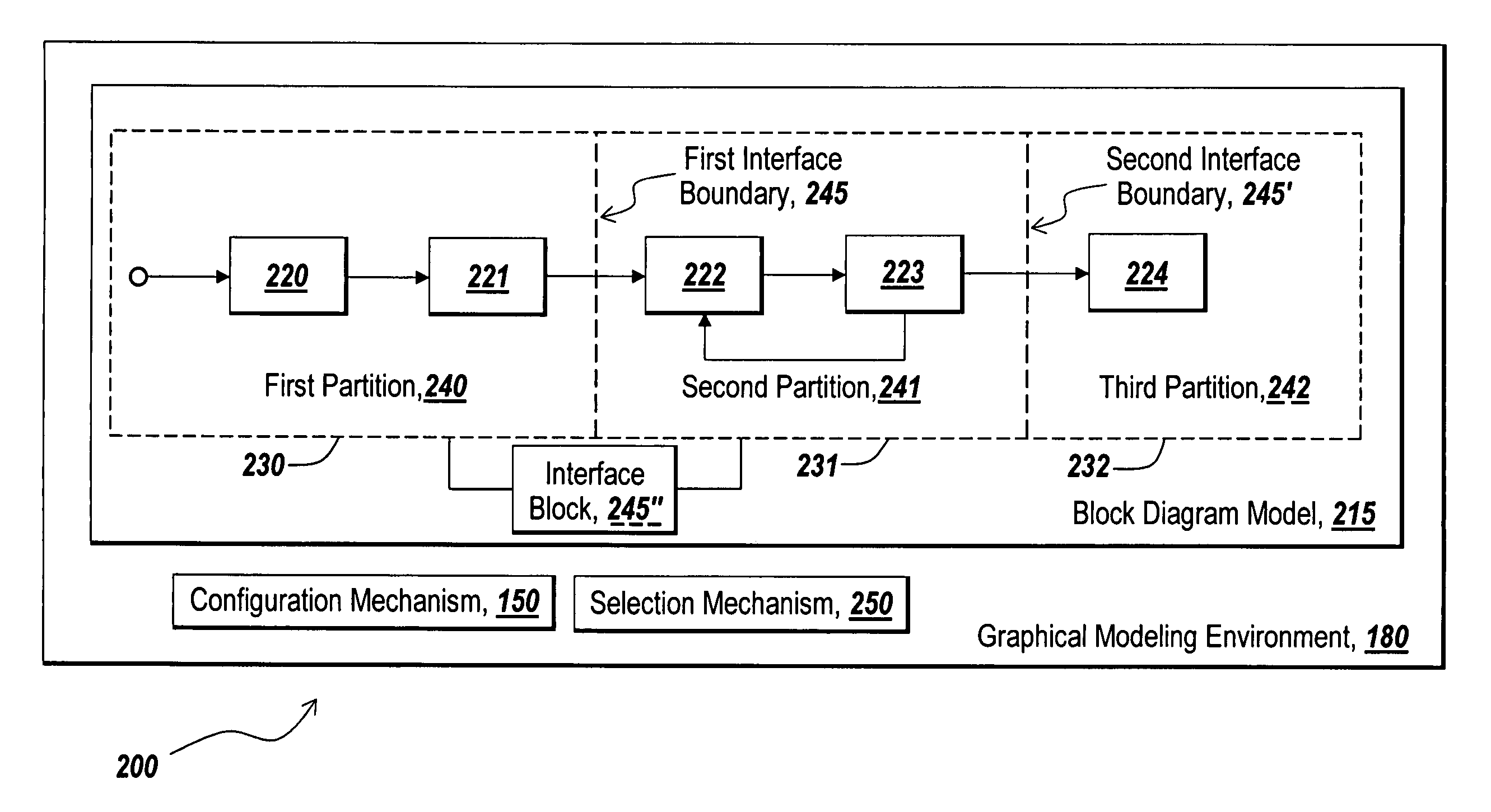
[0040]The illustrative embodiment of the present invention provides systems and methods for representing in a block diagram model a component interface between electronic components of a target computational hardware device. The system and methods also provide for automatically generating code from the block diagram model to implement the component interfaces bet...


PUM


Abstract

Method and systems are provided for representing interfaces between electronic components of a computational hardware device in a graphical model and automatically generating code from the graphical model to implement one or more component interfaces in the computational hardware device. A graphical modeling environment provides for the definition of interface boundaries to represent component interfaces between electronic components associated with partitions of a graphical model design. A code building tool automatically generates code from the graphical model to build executable instructions to run the component interfaces on the electronic components of the computational hardware device.

Description

RELATED APPLICATIONS[0001]This present application claims priority to U.S. Provisional Patent Application No. 60 / 611,615, entitled “Automatic Generation Of Component Interfaces For Heterogeneous Implementations Generated From A Block Diagram Model”, filed Sep. 20, 2004, which is incorporated herein by reference.TECHNICAL FIELD[0002]The present invention generally relates to technical computing, and, more particularly, to automatically generating code for interfaces between components of a computational hardware device from a design in a block diagram model.BACKGROUND INFORMATION[0003]Graphical modeling environments, such as the technical computing environment of MATLAB® from the MathWorks, Inc. of Natick, Mass., can provide a “model-based design” approach to designing an implementation, such as for embedded computational hardware. The term “model-based design” is used to refer to a graphical model acting as a design. A model-based design may be used as a design specification for an ...

Claims


Application Information

Patent Timeline
IPC IPC(8): G06F17/50G06F3/023
CPCG06F8/35G06F8/36
Inventor KOH, DAVIDOROFINO, II, DONALD PAUL
Owner THE MATHWORKS INC
Why Eureka
Try Eureka