Cooling device, manufacturing method, and manufacturing line for hot rolled steel band

a technology of hot rolled steel and cooling apparatus, which is applied in the direction of heat treatment apparatus, manufacturing tools, furnaces, etc., can solve the problems of insufficient cooling water volume, inability to cool, and further vertical waves, and achieve rapid and uniform cooling and transfer. stab

Inactive Publication Date: 2009-04-28
JFE STEEL CORP
View PDF22 Cites 17 Cited by
  • Summary
  • Abstract
  • Description
  • Claims
  • Application Information

AI Technical Summary

Problems solved by technology

However, the method described in Japanese Unexamined Patent Application Publication No. 62-259610 causes various problems as follows.
Cooling of such a tension free steel strip in this method causes further vertical waves.
As a result, a sufficient volume of cooling water is not applied and it is impossible to cool, for example, a steel strip of 3 mm in thickness at a cooling rate exceeding 200° C. / s.
(2) This method does not enable the top and bottom surfaces of the steel strip to be cooled at the same cooling rate.
Therefore, desired cooling is not performed because of a decrease in the flow velocity of the jetted cooling water.
Thus, uniform cooling in the width direction is not performed.
However, a large amount of cooling water is drained from the center toward the edges in the width direction of the steel strip after cooling, disrupting the cooling water flow at the edge in the width direction to lower cooling capability.
Thus, uniform cooling in the width direction is not performed.
Thus, uniform cooling in the width direction is not performed, either.
The cooling water jetted aslant to the steel strip travels a longer distance, thus greatly reducing the flow velocity to fail to efficiently cool the steel strip.
As described in (3), cooling capability is greatly affected by the jetted cooling water, so it is more difficult to uniformly cool the steel strip in the width direction.

Method used


Image

  • Cooling device, manufacturing method, and manufacturing line for hot rolled steel band
  • Cooling device, manufacturing method, and manufacturing line for hot rolled steel band
  • Cooling device, manufacturing method, and manufacturing line for hot rolled steel band

Examples


example

[0076]Using a production line for hot rolled steel strip shown in FIG. 14, which is provided with a cooling apparatus for hot rolled steel strip according to the present invention shown in FIG. 13, a sheet bar of carbon steel having a thickness of 30 mm and a width of 1,000 mm was rolled by a finishing mill having seven rolling stands at a transfer rate of 700 mpm and at a finishing temperature of 850° C. into a steel strip having a thickness of 3 mm. The steel strip was cooled to about 550° C. at a cooling rate of 700° C. / s, and then cooled to a coiling temperature of 500° C. using a conventional cooling apparatus 8. The water flow rate was 7,500 L / min·m2 for a cooling.-rate of about 700° C. / s.

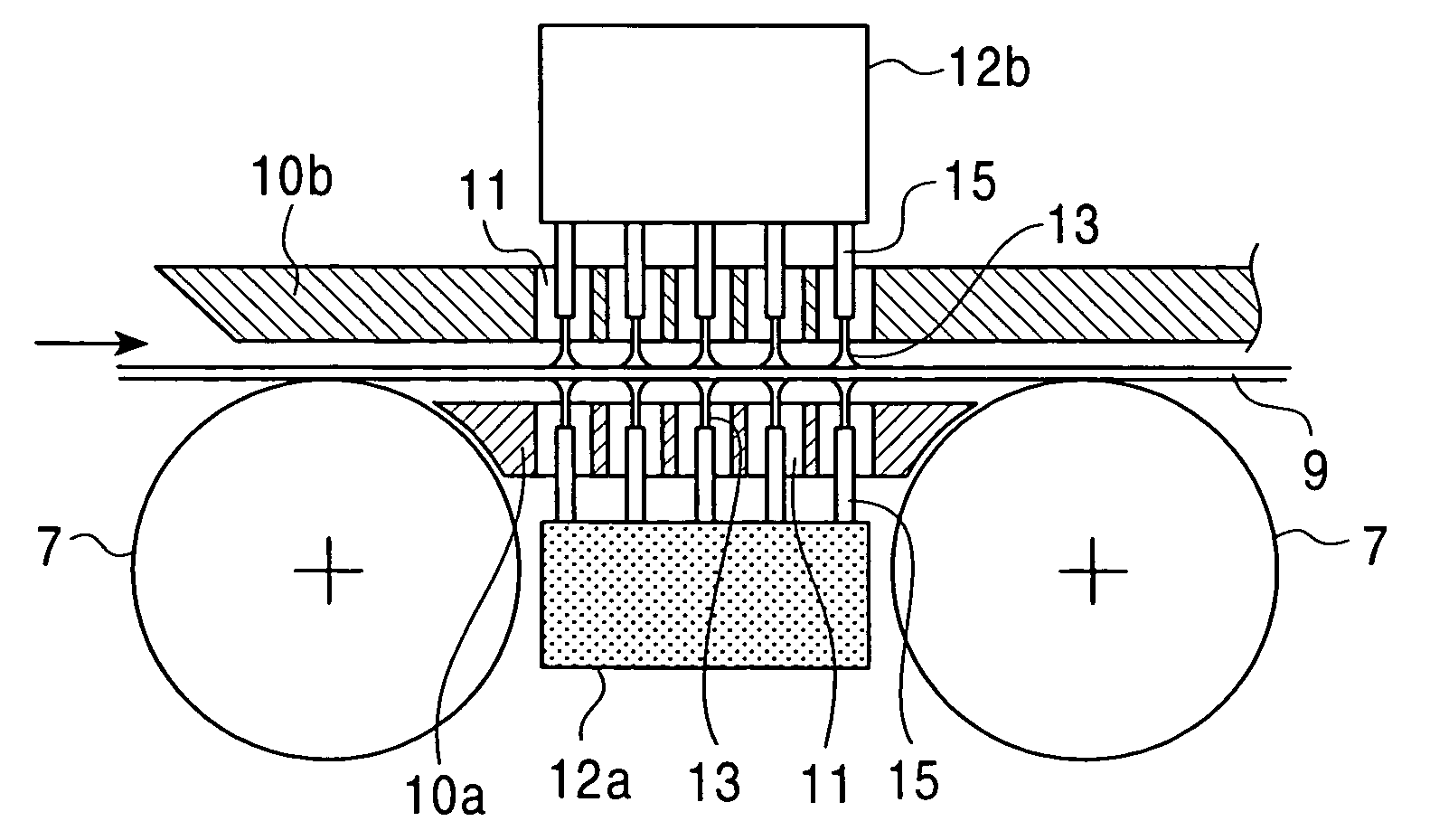
[0077]As shown in FIG. 13, bottom surface cooling means 4a comprises a plurality of transfer rollers 7 having a diameter of 300 mm which are disposed in the longitudinal direction at a pitch of 500 mm, bottom surface protective member plates 10a having a thickness of 25 mm which are disposed ...


PUM

PropertyMeasurementUnit
distanceaaaaaaaaaa
distanceaaaaaaaaaa
thicknessaaaaaaaaaa

Abstract

A cooling apparatus for a hot rolled steel strip comprising: top surface cooling means provided above a hot rolled steel strip which is transferred with transfer rollers; and a bottom surface cooling means provided below the hot rolled steel strip, each of the top surface cooling means and the bottom surface cooling means comprising: a protective member having at least one cooling water passage hole; at least one cooling water header opposing the hot rolled steel strip separated by the protective member; and cooling water jetting nozzles protruding from the cooling water header, wherein the tips of the cooling water jetting nozzles are disposed farther from the hot rolled steel strip than the surface, opposing the hot rolled steel strip, of the protective member.

Description

[0001]This application is the United States national phase application of International Application PCT / JP02 / 08113 filed Aug. 8, 2002.TECHNICAL FIELD[0002]The present invention relates to a cooling apparatus for hot rolled steel strip, a manufacturing method for hot rolled steel strip and a production line for hot rolled steel strip using the cooling apparatus.BACKGROUND ART[0003]In general, a hot rolled steel strip is manufactured by heating a slab to a predetermined temperature in a reheating furnace, hot rolling the heated slab into a sheet bar having a predetermined thickness using a roughing mill, hot rolling the sheet bar into a steel strip having a predetermined thickness using a finishing mill having a plurality of rolling stands, transferring and cooling the hot rolled steel strip on a run-out table using a cooling apparatus, and then coiling the steel strip on a coiler. The run-out table is a transfer apparatus provided downstream of the finishing mill to transfer the hot ...

Claims


Application Information

Patent Timeline
Patent Type & Authority Patents(United States)
IPC IPC(8): B21B27/06B21B39/00B21B39/10B21B45/02C21D1/667C21D8/02C21D9/573
CPCB21B45/0218B21B45/0233C21D1/667C21D9/573B21B45/0281C21D1/60C21D8/0263B21B45/02
Inventor FUJIBAYASHI, AKIOSASAKI, MASATOHINO, YOSHIMICHIWATANABE, ATSUSHI
Owner JFE STEEL CORP
Why Eureka
Try Eureka